Connections & wiring diagrams – Precision Digital PD6770 User Manual
Page 10
PD6770 Loop-Powered Process Meter
Instruction Manual
10
Connections & Wiring Diagrams
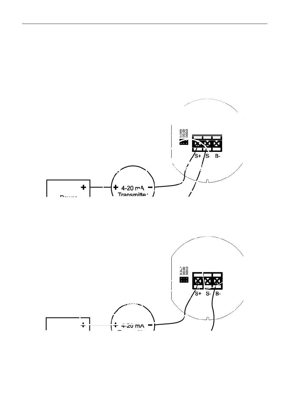
Signal connections are made to a three-terminal connector mounted on the rear of
the display module. The enclosure also provides one internal and one external earth
grounding screw. The 4-20 mA input with no backlight has a maximum voltage drop
of 1 V and is wired as shown in Figure 2. The loop-powered backlight configuration
requires a total maximum voltage drop of 4 V. The backlight option is recommended
for dim lighting conditions and is enabled when wired as shown in Figure 3.
Figure 2. PD6770 Input Connections without Backlight
Figure 3. PD6770 Input Connections with Loop-Powered Backlight