Precision Digital PD562 User Manual
Page 3
Nova Multi-Monitoring Software
Instruction Manual
3
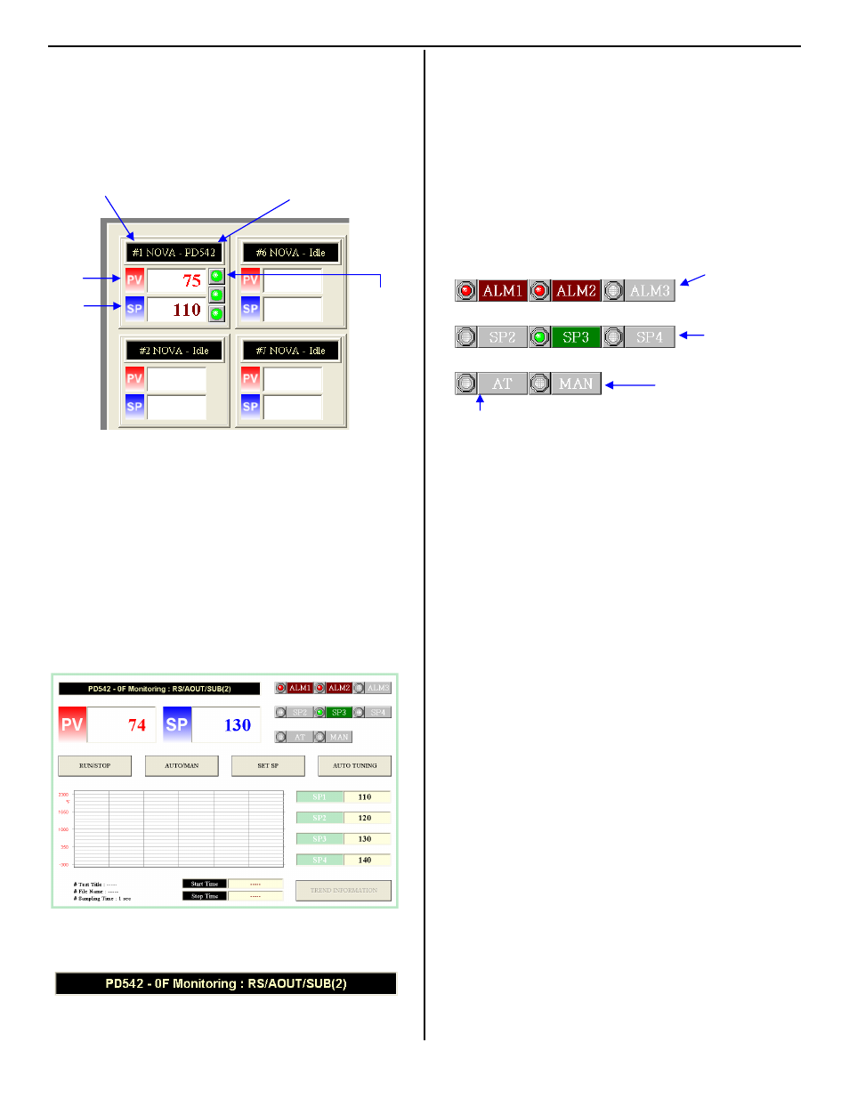
OVERVIEW MONITORING SCREEN
The overview window shows the present PV and SP
reading(s), alarm status, and address number(s) along
with the basic model number of each controller. The
graphic below indicates the different parts of the
overview window.
All 30 potential controller windows are displayed on the
overview screen. Addresses that are not active will
display “Idle”.
DETAILED OPERATION SCREEN
To access the detailed operation screen for any
controller being monitored, left-click on that controller’s
monitoring box in the overview screen. To return, left-
click on the PV/SP display or the black heading bar in
the detailed operation screen.
Note: The following screen is for a PD540 series Digital Controller.
Other series Nova controllers may have slightly different detailed
operation screen displays showing various details about the current
settings, programs, set points, LED indicators, and outputs.
Specific information about the controller is displayed in
the black heading at the top of the window.
This bar indicates information about the controller being
monitored. The basic model number of the controller is
displayed at the beginning. In addition, information about
the controller is indicated on the right. Some examples
are given here.
RS: RS-485 Communication Option
AOUT: Second analog output present
SUB(#): Number of optional relays
Alarm, SP, auto-tuning, and manual control indicators
are located in the upper right corner of the screen. Note
that these indicators may vary depending on the type of
controller being monitored.
The detailed operation screen allows for control as well
as monitoring. Dependant on the series of the contriller,
various buttons will be located in the detailed operation
screen. Some examples and their functions are given
below.
RUN/STOP:
Changes the controller from running
mode to stop mode. (PD540 Series)
AUTO/MAN:
Changes from PID output control to
manual output control. (PD540 Series)
SET SP:
This button allows for the setup of the 4
set points and selects which set point is
active. (PD540 Series)
AUTO TUNING: This button activates auto-tuning.
(PD540 Series)
A/T:
This button activates auto-tuning.
(PD550 Series)
PROG1/2:
These buttons activate set point
program one or two. (PD550 Series)
RESET:
This will end the current program and
return the controller to stop mode.
(PD550 Series)
HOLD:
This will turn program hold on and off,
stopping the program at the currently
displayed set point. (PD550 Series)
STEP:
This will skip to the next program
segment. (PD550 Series)
TREND
INFORMATION:This will display information about the
current graph.
Controller Address
Model Number
Process
Variable
Set Point
Alarm 1-3
Status
Off = Green
On = Red
Alarm 1-3 Status:
“On” when in
alarm condition
Active set point # 3
“On” when manual
output control is active
“On” when auto-tuning