Fig. 1, Fig. 2, Fig.1 – Medal Sports SMUS1458415 User Manual
Page 8: Fig.2
www.themdsports.com
1458415
7
(Continúe en la siguiente página.)
(Continued on the next page.)
Español
English
INSTRUCCIONES DE ENSAMBLAJE
ASSEMBLY INSTRUCTIONS:
1.
Find a clean, level place to begin the assembly of
your Soccer Table Game. We recommend that two
adults work together to assemble this Soccer Table
game.
2. Remove all the parts from the box and verify that you
have all of the listed parts as shown on the parts list
page. Carefully cut or tear the four corners of the box
so that the bottom of the box can be used as your
work surface.
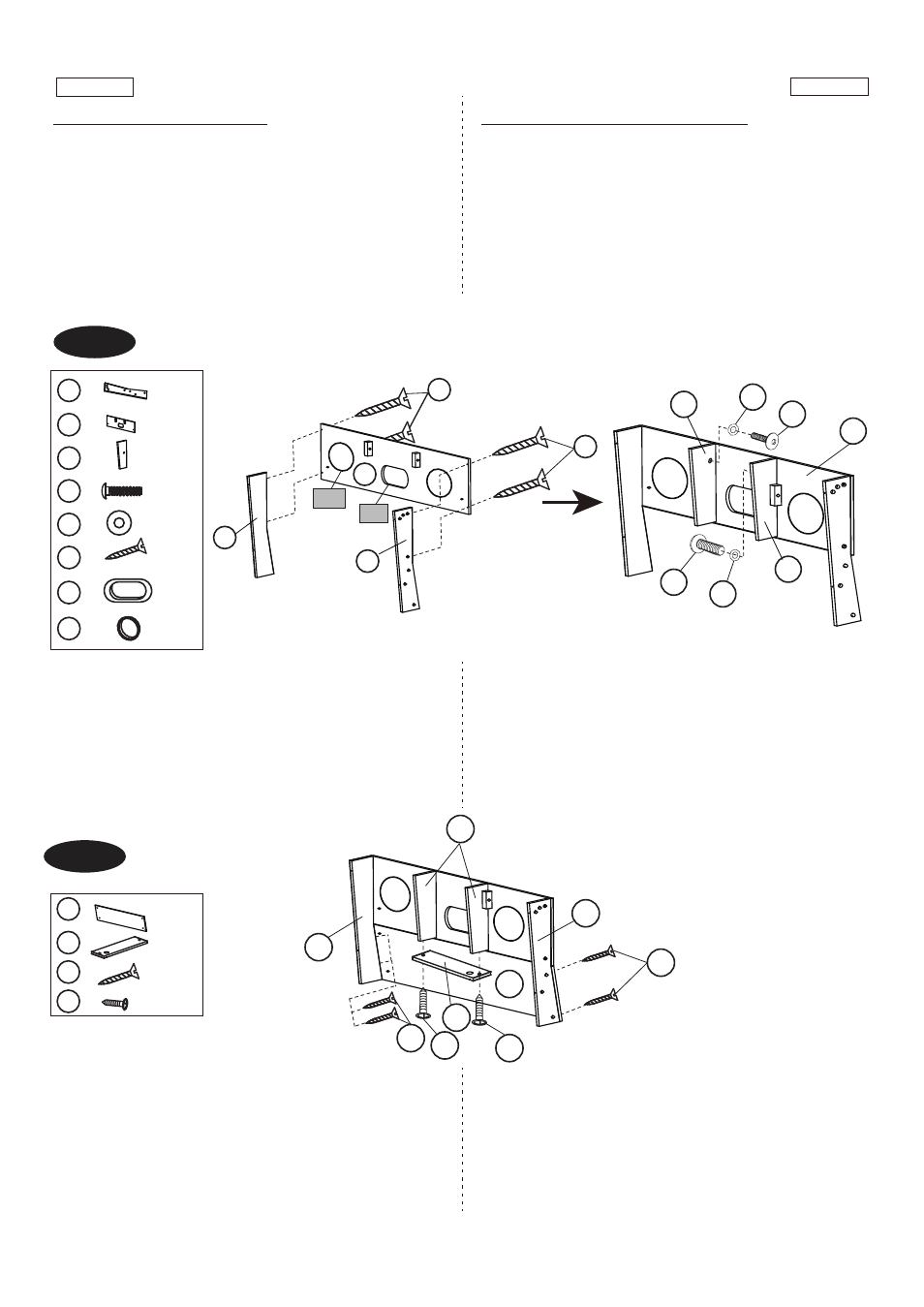
FIG.1
3. Attach two Connection Side Panel (#10) to one Goal
Box (#11) using four Bolts (#26) per Goal Box.
See
FIG. 1
4. Attach two Goal Box Side Panel (#12) to one Goal Box
(#11) using two Bolts (#21) and two Washers (#24) per
Goal Box.
See FIG. 1
FIG. 1
1. Encuentre un lugar limpio, plano para comenzar el
montaje de su Juego de Mesa de Fútbol.
Recomendamos montar por dos adultos juntos para
este juego de mesa de Fútbol.
2. Quite todas las partes desde la caja y verifique que
están todas las partes catalogadas como mostrado en
la página de lista de partes. Con cuidado de cortar o
rasgar los cuatro rincones de la caja de modo que
el fondo de la caja podría ser usado como su superficie
de trabajo.
FIG.1
3. Adjunte los 2 Paneles Lateral de Conexión (#10) a 1
Caja de Gol (#11) usando 4 Cerrojos (#26) por Caja
de Gol.
Vea la FIG. 1.
4. Adjunte 2 Panel Lateral de Caja de Gol (#12) a 1
Caja de Gol (#11) usando 2 Cerrojos (#21) y 2
Arandelas (#24) por Caja de Gol.
Vea la FIG. 1.
FIG.2
5. Adjunte 1 Panel de Pierna – A (#9) al Panel Lateral
de Conexión (#10) usando 4 Cerrojos (#26) por
Panel de Pierna – A. Vea la FIG. 2.
6. Adjunte 1 Panel Final de Caja de Gol (#14) al Panel
Lateral de Caja de Gol (#12) usando 2 Cerrojos (#30)
por Caja de Catcher debejo de Panel. Vea la FIG. 2.
FIG. 2
FIG.2
5.
Attach one Leg Panel-A (#9) to Connection Side Panel
(#10) using four Bolts (#26) per Leg Panel-A.
See FIG. 2
6.
Attach one Goal Box End Panel (#14) to Goal Box Side
Panel (#12) using two Bolts (#30) per Catcher Box under
Panel.
See FIG. 2
X 2
11
X 8
26
X 2
P4
X 4
P5
X 4
21
X 4
24
X 4
12
X 4
10
P5
11
26
26
10
10
P4
11
21
21
24
24
12
12
X 8
26
X 4
30
X 2
9
X 2
14
12
10
10
26
26
30
30
9
14