Valve disassembly, Re-assembly, Testing – Marwin Valve 10000 Series Soft Seated Ball Valve User Manual
Page 3: Troubleshooting
Valve Disassembly
A. To inspect and/or Replace Body Seals, Seats,
Packing & Ball
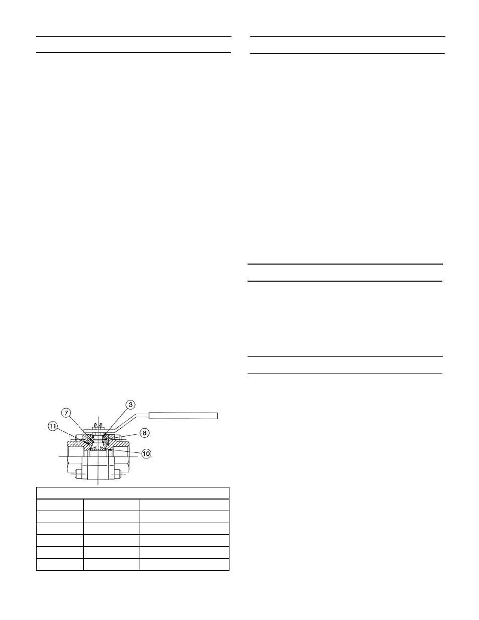
Reference cross section for part identification
Valve must be in the open position.
1.
Remove valve from line.
2.
Remove bolts (11) securing end cap and separate
3.
end cap (2) from body (1).
Close the valves and remove ball (3), seats (7) and
4.
body seal (15). Be careful not to damage the ball.
Remove the handle nut (13), handle (12), stem nut
5.
(14), gland (5), thrust washer (8), and packing (9).
Push the stem (4) into the body (1). Remove thrust
6.
washer (8) from stem.
B. Inspection and Replacement
With the valve completely disassembled, clean and
examine all components.
The surface of the ball should be free from any de-
1.
fect. If any are found, the ball should be replaced.
Using a defective ball will be extremely detrimental
to valve performance.
Seats. Replacement of seats is recommended.
2.
Stem seals and body seals. Should be discarded
3.
and replaced.
Remaining components of the valve. After clean-
4.
ing, carefully examine for wear, corrosion and
mechanical damage. Replace all defective parts.
Clean inside of body and stem housing. Light
5.
grease, compatible with line fluid, can be used on
ball, seals and stem surface.
Note: A spare parts list is available for this valve.
Please refer to explosion view below for identifica-
tion. Please specify specific valve number to ensure
proper parts are ordered. Marwin Valve does not take
responsibility for incorrectly ordered spare parts.
Re-Assembly
A. Stem
Replace thrust washer (8) and O-Ring (18) then
1.
insert the stem from inside of body.
Install stem packing (9), thrust washer (8), gland
2.
(5), spring washers (6), stop plate (16) and stem
nut (10), and tighten until snug, then one-half turn.
To avoid rotation of stem, insert the handle and
ball.
Install handle (12) and handle nut (13) then tighten.
3.
B. Ball, Seats, and Seals
Install seat (7) in body (1).
1.
Place the stem (4) in closed position and insert the
2.
ball (3), aligning groove in ball with bottom of stem.
Position the ball in the open position, then insert
3.
the seat (7), body seal (15) and end cap (2).
Hand tighten all bolts (11).
4.
Tighten nuts to recommended values using an
5.
alternating/opposing pattern with no more than 1/4
turn on each nut before alternating.
Testing
After completing the reassembly, check that valve
1.
operates smoothly by opening and closing valve
several times.
If entire valve was removed from line and if facili-
2.
ties area available, test the ball valve to appropri-
ate specifications.
Troubleshooting
A. Stem Leakage
Leakage in the stem packing area may be eliminat-
1.
ed by increasing the torque on the stem nut (14)
in one-quarter turn increments. If leakage persists,
replace stem packing (9).
B. Body Seal Leakage
Check the torque of the body bolts (11) according
1.
to Torque Table.
Spare Parts List
Item #
Quantity
Part Name
7
2
Seats
8
2
Thrust Washer
9
1
Packing
15
2
Body Seal
18
1
O-Ring