Connectors layout – Eurotech Appliances COM-1460 User Manual
Page 14
14
PC/104-Plus – COM-1460 Module
Connectors Layout
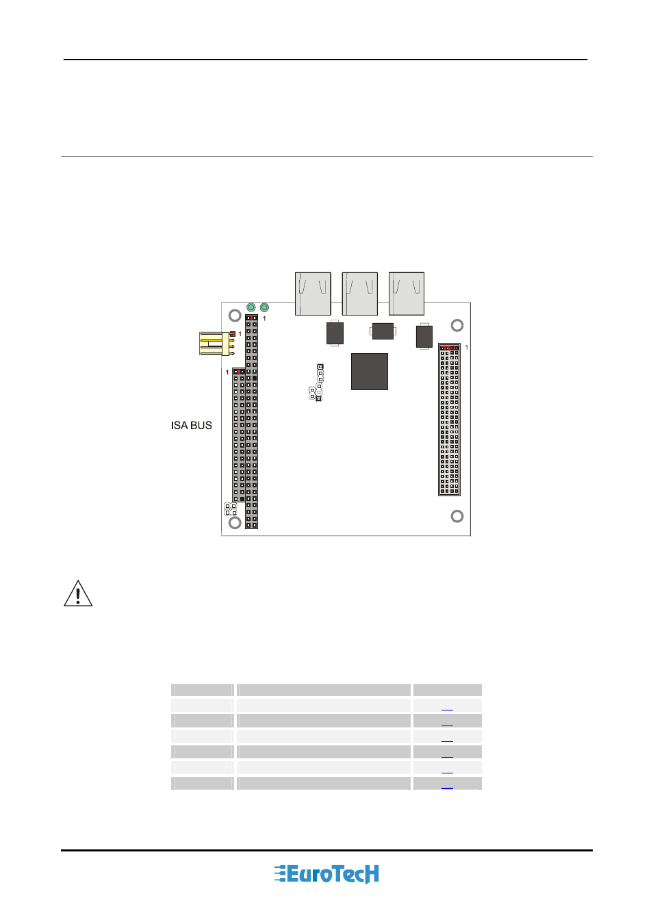
The following figure shows the connectors with their layout and describes their function.
Firewire
Main Power
Firewire Firewire
J9
J10
J8
J7
J3
PCI BUS
J1 J2
Figure 3.
Connectors layout
Note: in the above figure, a red square pad indicates pin 1 of each connector.
The table below lists the name of the connectors with their function and the reference page.
Table 2.
Connector Functions
Connector
Function
Pag.
J1-J2
ISA BUS
J3
PCI BUS
J7
Firewire 1
J8
Firewire 2
J9
Firewire 3
J10
Main Power