Jumper layout and configuration – Eurotech Appliances COM-1460 User Manual
Page 10
10
PC/104-Plus – COM-1460 Module
Jumper Layout and Configuration
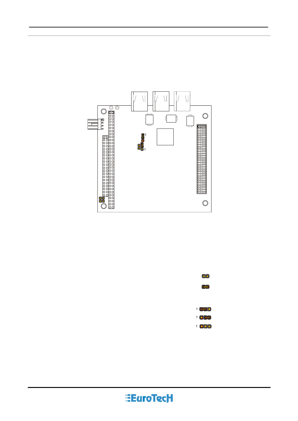
The figure below shows the jumper layout of the COM-1460 module.
In the figure below, the jumpers are indicated as
JP
followed by the jumper's number, while pin 1 of every
three pin jumper is indicated by a red square pad.
JP3
JP2
JP5
JP4
JP1
Figure 2.
Jumpers on the COM-1460 module
The following jumpers are located on the module:
Three 2-pin jumpers which can be set as follows:
pin 1 and pin 2 not connected (which will be indicated as ‘Open’)
pin 1 connected to pin 2 (which will be indicated as ‘Closed’)
Two 3-pin jumpers which can be set as follows:
pin 1 connected to pin 2 (which will be indicated as ‘1-2’)
pin 2 connected to pin 3 (which will be indicated as ‘2-3’)
no pins connected (Open). This setting is not allowed
= 2-3
= 1-2
= Open
= Closed
= Open