Emerson BP7251 User Manual
Page 9
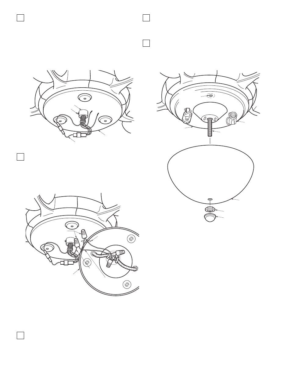
31. Using the 5/64” hex wrench (supplied), loosen the
setscrew in the collar on the light kit adapter
assembly. Then pass the connectors and the wires
from the motor shaft through the collar (Figure 18A).
Screw the adapter assembly onto the motor shaft
and then tighten the setscrew to secure the adapter
assembly to the motor shaft. Connect the
connectors from the motor shaft using the jumper
assembly (supplied). Verify that the connectors are
securely engaged.
32. Securely connect the black wire from the light kit
plate assembly to the blue wire from the motor shaft
using a wire connector (supplied) (Figure 19A).
Connect the white wire from the plate assembly to
the white wire form the motor shaft using a wire
connector (supplied).
NOTE: When installing the light kit plate
assembly, position the wires and wire connectors
in the raised center portion of the plate assembly.
Do not pinch wires between the light kit plate
assembly and the adapter assembly.
33. Secure the light kit plate assembly to the light kit
adapter assembly by threading three
5/32-32 x 3/16” phillips head screws (supplied) into
the threaded holes in the adapter assembly
(Figure 20A).
9
LIGHT KIT
ADAPTER ASSEMBLY
JUMPER
ASSEMBLY
SETSCREW
COLLAR
Figure 18A
BLUE
WIRE
LIGHT KIT
PLATE ASSEMBLY
WIRE
CONNECTORS
BLACK
WIRE
WHITE WIRES
Figure 19A
LIGHT KIT
PLATE ASSEMBLY
SOCKET
THREADED NIPPLE
GLASS
SHADE,
LOWER
FINIAL
NUT
HEX NUT 1/8-27
5/32-32 x 3/16"
PHILLIPS HEAD
SCREW (3)
Figure 20A
34. Install two candelabra base lamps in the sockets of
the light kit adapter plate (Figure 20A):
Model CF2600 - 15-Watt Maximum
Model CF2650 - 25-Watt Maximum
35. Position the glass shade over the threaded nipple
in the light kit plate assembly (Figure 20A). Seat
the glass shade evenly over the plate assembly
and securely install the hex nut and finial nut
(supplied) on the threaded nipple.