Fig.2 fig.3 fig.4, Fig.1, Installation – Sealey CH4200 User Manual
Page 2
Original Language Version
cH4200 Issue: 1 - 17/06/11
3.1.
Ventilation
3.1.1. It is essential that adequate ventilation is provided and maintained in the room where the heater is installed. the heater needs a fresh
air supply to run efficiently. ensure that any ventilation grilles in the room are open and not blocked. If there are no ventilation grilles,
a window or outside door will need to be opened. If the room begins to feel stuffy, more ventilation may be needed. see required room
ventilation opening below.
3.1.2. do not place the heater in a corridor or where it is likely to be exposed to strong draughts.
3.1.3. the heater has an oxygen depletion sensor (ods) fitted. this will shut the heater down if not enough fresh oxygen content is available.
3.1.4. If the heater shuts down, do not relight it until extra ventilation is sourced.
3.1.5. the heater
MUST NOT be used in rooms having less than 15m³ volume (30m³ for living rooms). see table below.
HEAT SETTING
REQUIRED ROOM VOLUME
REQUIRED ROOM VENTILATION OPENING
MIn.
15m³
105cm²
Med.
28.5m³
105cm²
Max.
42m³
105cm²
3.1.6. carbon Monoxide (co) is a highly poisonous gas which can be produced if the heater is not working correctly. It is difficult to recognise as
it has no colour, odour or taste. some symptoms of co poisoning are:
weakness, dizziness, nausea, vomiting, (severe) headache, convulsions, coma, slowed respiration, depressed heart action, tightness
across the forehead. If the exposure is severe it can cause death.
If the heater is showing any signs of the following it could be producing carbon Monoxide:
ceramic burner panels are dull, gas burns with a blue haze, soot deposits on the burner panels, burner panels or cement fixings are
damaged, heater does not burn quietly. If there are any of these signs and/or any of the symptoms present, switch the heater off and
have it checked by a qualified gas engineer.
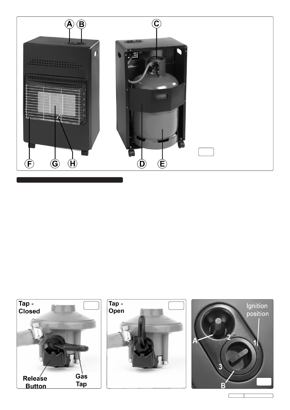
3. INSTALLATION
fig.2
fig.3
fig.4
A - Ignition button
B - Heat control dial
c - Gas regulator
d - Gas cylinder retainer
e - Gas cylinder (not included)
f - Heater Grille
G - ceramic Burner Panels
H - Pilot light
fig.1