Assembly, Consumer, Assembly / pre-operation – Electrolux OHV User Manual
Page 8
8
9
Read these instructions and this manual in its entirety before you attempt to assemble or operate your new snow thrower.Your
new snow thrower has been assembled at the factory with the exception of those parts left unassembled for shipping
purposes. All parts such as nuts, washers, bolts, etc., necessary to complete the assembly have been placed in the parts
bag. To ensure safe and proper operation of your snow thrower, all parts and hardware you assemble must be tightened
securely. Use the correct tools as necessary to ensure proper tightness.
REMOVE SNOW THROWER FROM CARTON
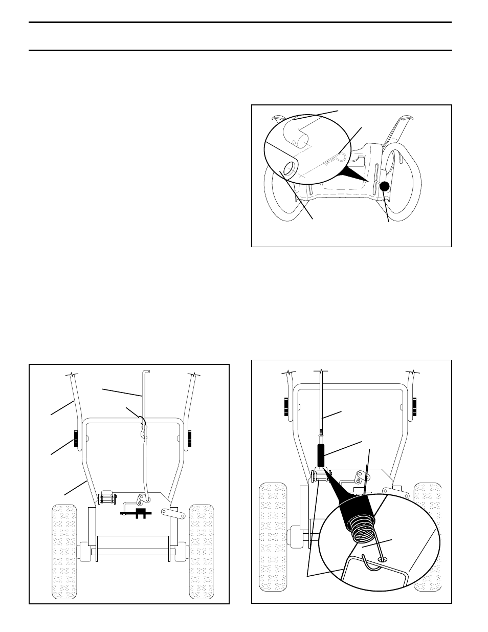
INSTALL TRACTION DRIVE CONTROL ROD
(See Figs. 3 and 4)
The traction drive control rod has the long loop on the end
of the spring as shown.
1. Slide rubber sleeve up rod and hook end of spring into
pivot bracket with loop opening down as shown.
2. Remove retainer spring from top end of rod.
3. With top end of rod positioned under left side of control
panel, push rod down and insert top end of rod into hole
in drive control bracket. Secure with retainer spring.
1. Remove all accessible loose parts and parts boxes
from carton.
2. Cut down all four corners of carton and lay panels
flat.
3. Remove all packing materials except plastic tie holding
speed control rod to lower handle.
4. Remove snow thrower from carton and check carton
thoroughly for additional loose parts.
HOW TO SET UP YOUR SNOW THROWER
TOOL BOX (See Fig. 12)
A toolbox is provided on your snow thrower. The toolbox
is located on top of the belt cover. Store the extra shear
bolts, nuts and multi-wrench provided in parts bag in the
toolbox.
NOTE: The multi-wrench may be used for assembly of the
chute rotator head to snow thrower and making adjustments
to the skid plates.
UNFOLD UPPER HANDLE
1. Raise upper handle to the operating position and tighten
handle knobs securely.
INSTALL SPEED CONTROL ROD (See Figs. 1 and 2)
1. Remove plastic tie securing rod to lower handle.
2. Remove retainer spring from top end of rod.
3. Insert rod into speed control bracket and secure with
retainer spring.
SPEED CON-
TROL ROD
HANDLE
KNOB
LOWER
HANDLE
PLASTIC TIE
UPPER
HANDLE
FIG. 1
TRACTION DRIVE
CONTROL ROD
PIVOT
BRACKET
RUBBER
SLEEVE
LOOP
OPENING
DOWN
FIG. 3
SPEED CONTROL ROD
SPEED CONTROL
BRACKET
RETAINER
SPRING
SPEED CONTROL
LEVER
FIG. 2
CONSUMER
ASSEMBLY / PRE-OPERATION
For Husqvarna Parts Call 606-678-9623 or 606-561-4983
www.mymowerparts.com