Replacing the stirrer drive motor, Removing motor and sprocket, Replacing the stirrer drive shaft – England's Stove Works 10-CPM User Manual
Page 22
IMPORTANT! READ AND FOLLOW ALL INSTALLATION AND MAINTENANCE INSTRUCTIONS, INCLUDING
CLEANING THE UNIT AS SPECIFIED, AND REPLACING GASKETS ANNUALLY, AND PARTS AS NEEDED.
ENGLAND’S STOVE WORKS IS NOT RESPONSIBLE FOR ANY DAMAGE OR INJURY INCURRED DUE TO NEGLECT, OR DUE
TO UNSAFE INSTALLATION OR USAGE OF THIS PRODUCT. CALL TECHNICAL SUPPORT WITH QUESTIONS.
22
Replacing the Stirrer Drive Motor
1.
Locate the access panel on the right side of stove (looking from front of stove).
2.
Remove the four (4)
5
/
16
“ mounting screws.
3.
Locate the drive motor mounting bracket which is secured by two (2)
1
/
2
“ bolts (C). Loosen these
bolts.
4.
Locate the
1
/
2
“ chain adjustment bolt (A) on the left side of the drive motor. Loosen this bolt.
5.
Remove the two (2)
1
/
2
“ mounting bolts (C).
6.
Slide drive motor mounting bracket toward the front of the stove and remove chain from sprocket
(B).
7.
Remove bracket and motor through access panel and disconnect the two power leads from motor.
Removing Motor and Sprocket
1.
Remove
1
/
2
“ chain adjustment bolt (A).
2.
Locate the
3
/
32
“ Allen Head setscrew on the sprocket and loosen.
3.
Remove sprocket (B) from motor shaft.
4.
Remove the four (4) drive motor mounting screws (D) with a
5
/
16
“ nutdriver or socket.
NOTE: When re-installing the sprocket, align the
3
/
32
“ Allen Head setscrew with the flat side of the
motor shaft.
Replacing the Stirrer Drive Shaft
1.
Remove cast plug from right side (looking from the front of the stove) using a
3
/
16
“ Allen Wrench.
2.
Locate the access panel on the right side (looking from front of stove).
3.
Remove the four (4)
5
/
16
“ mounting screws (D).
4.
Locate the drive motor mounting bracket which is secured by two (2)
1
/
2
“ bolts (C). Loosen these
bolts.
5.
Locate the
1
/
2
“ chain adjustment bolt (A) on the left side of the drive motor. Loosen this bolt.
6.
Remove chain from Stirrer Shaft sprocket (B).
NOTE: It may be necessary to rotate the shaft by hand to access the set screw.
7.
Locate the
3
/
32
“ Allen Head setscrew on the sprocket and loosen.
8.
Remove
5
/
8
“ locking collar from Stirrer shaft inside the unit using a
5
/
32
“ Allen Wrench.
9.
Remove shaft by pulling to you from outside the stove.
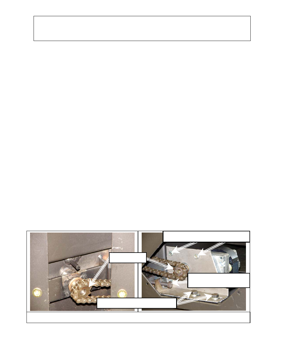
Illustration 5 - Motor, Shaft and Sprockets
(A)
1
/
2
" Chain adjustment
bolt
(B) Sprockets
(C)
1
/
2
" Mounting bracket bolts
(D)
5
/
16
" Motor mounting screws
As with any maintenance concerning this unit, be sure the unit is “OFF” and has completed the Shut-
Down cycle BEFORE beginning. Be aware that metal parts in the firebox can remain HOT long after
the fire has gone out and EVEN after the Shut-Down cycle is complete. Always use extreme caution
when handling potentially hot stove parts, even if you think they should be cold.