Installing the ms-cefb – Magnum Energy Filter Box (MS-CEFB) User Manual
Page 7
© 2014 Magnum Energy, Inc.
6
Installation
Installing the MS-CEFB
Prior to installation of the fi lter box, the inverter/charger must be prepared.
To prepare the inverter (Figure 5, Stage I):
1. Remove the inverter’s AC access cover (will need access to inside the
inverter to remove the DC ground connection and to wire AC connections).
2. Remove the inverter’s DC positive and negative terminal nuts/washers.
3. Remove the DC ground connection from the bottom left corner on the
front side of the inverter (reach into the AC terminal block compartment
to secure the hex nut while unscrewing the bolt on the outside of the
inverter using a 7/16” wrench/nut driver). Refer to Figure 6.
4. Remove the two #25 Torx screws that hold the inverter cover to the
base—located on each side of the inverter’s front.
To prepare the MS-CEFB fi lter box:
5. Detach the top cover of the fi lter box by removing the four #25 Torx
screws that secure the cover to the base.
6. Determine the AC and DC wiring through the fi lter box, and then remove
the appropriate knockouts (Figure 3).
Note: Magnum does not provide additional strain reliefs or conduit for
the knockout holes; to add either, you must supply the hardware.
To attach the MS-CEFB to the inverter (Figure 5, Stages II & III):
7. Attach
the
fi lter box to the inverter using the two #25 Torx screws that
were removed from the inverter cover in Step 4. Ensure the fi lter box’s
DC busbars align over the inverter’s positive and negative DC terminals.
8. Secure
the
fi lter box’s mounting fl anges—preferably to the same mount-
ing surface used for the inverter.
9. Re-attach the DC ground connection removed in Step 3—the ground’s
Hex screw fi ts through the inner fl ange on the fi lter box (Figure 6).
10. Re-attach and tighten the inverter’s DC positive and negative terminal
nuts/washers that were removed in Step 2—securing the fi lter box’s
DC busbars to their respective DC terminals on the inverter. Torque to
between 13.6 and 16.3 N-m (10 to 12 ft lbf).
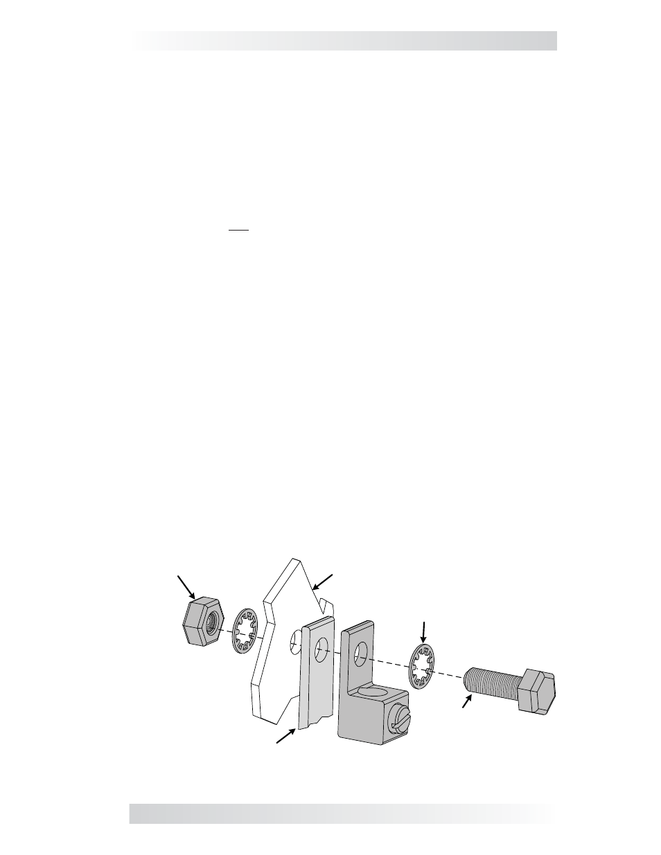
Figure 6, Re-Attaching the DC Ground Hardware
* Use 7/16"
wrench (or socket)
¼
-20 Hex nut*
Ground lug
Int. tooth
¼”
lock washer (x2)
¼
-20 x
¾
Hex screw*
Inverter
MS-CEFB
inner flange