Installation, Ferrite core communications cable – Magnum Energy Filter Box (MS-CEFB) User Manual
Page 11
© 2014 Magnum Energy, Inc.
10
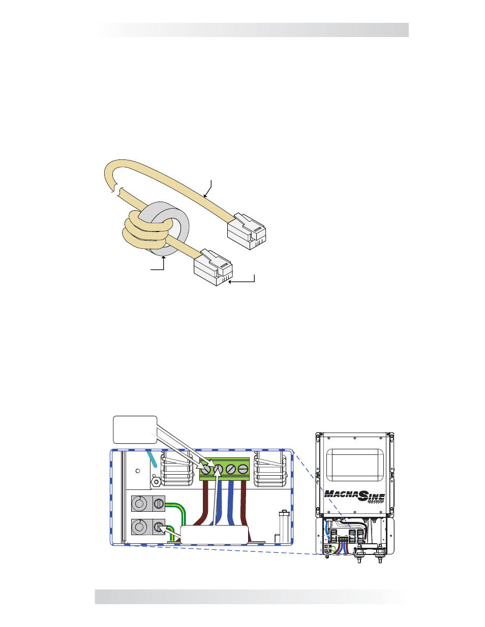
Blue
Brown
AC Output
230 VAC
(± 5%)
Neutral to Ground
< 0.5 VAC
Figure 10, AC Voltage Checks
Installation
To attach the ferrite core to a communication cable (Figure 9):
1. For each communication cable, route one end through the ferrite core
and wrap it several times around/through the core. There needs to be
at least three full turns around the ferrite core.
2. While wrapping the cable around the core, ensure the core is located as
close as possible to one end of the cable [within 2.5 to 5 cm (1-2 inches)
from the end]. The result should look something like Figure 9 below.
Note: Once the core is attached to the cable, plug the core-connected end of
the cable into the appropriate RJ11 port (Stack/Accessories, Remote, Network,
or BTS) on the inverter.
Figure 9, Ferrite Core Attached to a Communication Cable
Ferrite
Core
Communications
Cable
Note: This end to be
connected to inverter port.
Note: Multiple cables can be wrapped
around a single ferrite core, but each
should have three full turns – ensure
each goes in same direction around core.
Final Inspection
After all electrical connections to the inverter, batteries, AC source, and
sub-panel have been completed, follow the steps for the Functional Test as
directed in your inverter owner’s manual.
Note: When verifying the correct DC voltage, check the fi lter box’s positive
and negative DC terminals with a multimeter. When verifying the correct AC
output voltage, check the fi lter box’s AC terminal block NEUT OUT, HOT OUT,
and GROUND poles with a voltmeter (Figure 10 below).
Once your system passes all the steps, attach and secure the fi lter box’s cover.