Pin descriptions pin assignments, Pin # name description – Linx Technologies TXM-900-HP3-xxx User Manual
Page 3
Page 5
Pin #
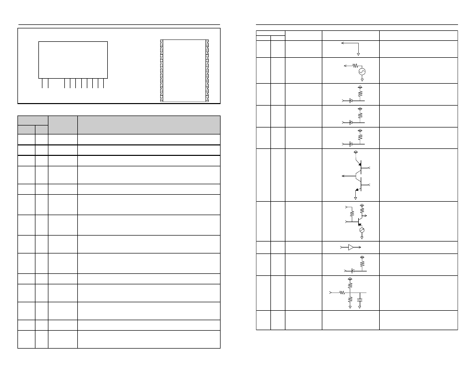
Analog Ground
50-ohm RF Output
Channel Select 0
Channel Select 1 /
Serial Select Clock
Channel Select 2 /
Serial Select Data
Clear-to-Send
Output
Mode Select
Voltage Input 2.8-13V
Power Down
(Active Low)
Digital / Analog Input
GND
ANT
CS0
CS1 /
SS CLOCK
CS2 /
SS DATA
PDN
CTS
MODE
DATA
V
CC
1, 3
13, 20
2
5
6
7
9
8
11
12
4,
14-19,
21-24
10
1
2
3
4
5
7
6
9
10
8
50
Ω
RF
Out
CTS
Out
PDN
430k
V
CC
SMD Pinned
NC
SMD (Only)
No Electrical Connection
100k
160k
510k
20pF
Name
Equivalent Circuit
Description
CS0
25k
μ
CS1
25k
μ
CS2
25k
μ
MODE
25k
μ
Page 4
PIN DESCRIPTIONS
PIN ASSIGNMENTS
GND
ANT
CS0
CS1 / SS CLOCK
CS 2 / SS DATA
CTS
PDN
VCC
MODE
DATA
1
2
3
4
5
6
7
8
9
10
GND
ANT
GND
NC
NC
GND
NC
NC
NC
CS2 / SS DATA
NC
CS0
CS1 / SS CLOCK
CTS
NC
NC
1
2
3
4
5
6
7
8
17
18
19
20
21
22
23
24
PDN
VCC
MODE
NC
GND
DATA
NC
NC
9
10
11
12
13
14
15
16
Figure 7: HP3 Series Receiver Pinout
Pin #
Name
Description
SMD SIP
1
1
GND
Analog Ground
2
2
ANT
50-ohm RF Output
3
GND
Analog Ground (SMD only)
4
NC
No Electrical Connection. Soldered for physical support
only.
5
3
CS0
Channel Select 0
6
4
CS1 / SS
CLOCK
Channel Select 1 / Serial Select Clock. Channel Select 1
when in parallel channel selection mode, clock input for
serial channel selection mode.
7
5
CS2 / SS
DATA
Channel Select 2 / Serial Select Data. Channel Select 2
when in parallel channel selection mode, data input for
serial channel selection mode.
8
6
CTS
Clear-To-Send. This line will go high when the transmitter
is ready to accept data.
9
7
PDN
Power Down. Pulling this line low will place the transmitter
into a low-current state. The module will not be able to
transmit a signal in this state.
10
8
V
CC
Supply Voltage
11
9
MODE
Mode Select. GND for parallel channel selection, V
CC
for
serial channel selection
12
10
DATA
Digital / Analog Data Input. This line will input the
modulated digital data or analog signal.
13, 20
GND
Analog Ground (SMD only)
14-19,
21-24
NC
No Electrical Connection. Soldered for physical support
only. (SMD only)
Surface-Mount Transmitter
Pinned Transmitter
Figure 8: Pin Functions and Equivalent Circuits