Regnvtxto, Regnvnetgrp, Regnvusecrc – Linx Technologies TRM-915-DTS User Manual
Page 14: Regtxto, Regnetgrp, Regusecrc
– –
– –
22
23
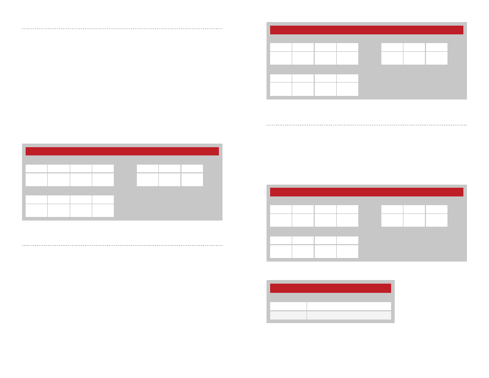
CRC Control - Address = 0x53; NV Address = 0x08
The DTS Series protocol includes a Cyclic Redundancy Check on the
received packets to make sure that there are no errors. Any packets with
errors are discarded and not output on the UART. This feature can be
disabled if it is desired to perform error checking outside the module. Set
the register to 0x01 to enable CRC checking, or 0x00 to disable it. The
default CRC mode setting is enabled. Figure 26 shows examples of the
commands and Figure 27 shows the available values.
Transmit Wait Timeout - Address = 0x50; NV Address = 0x05
When a byte is received from the UART, the module starts a timer that
counts down every millisecond. The timer is restarted when each byte is
received. The value for this setting is the number of milliseconds to wait
before transmitting the data in the UART receive buffer. The default setting
for this register is 0x10 (~16ms delay).
If the timer reaches zero before the next byte is received from the UART,
the module begins transmitting the data in the buffer. This timeout value
should be greater than one byte time at the current UART data rate.
If the timeout value is set to 0x00, the transmit wait timeout is deactivated.
In this case, the transceiver waits until a number of bytes equal to the MTU
have been received by the UART. All of the bytes are sent once the MTU
has been reached. Figure 24 shows examples of the commands.
Network Group - Address = 0x51; NV Address = 0x06
Modules can be grouped into networks. Although only modules with the
same network group ID can communicate, modules in different network
groups but on the same RF channel still coordinate transmissions through
the CSMA mechanism. Valid values for this register are decimal 0 to
127. The default group setting is 0. Figure 25 shows examples of the
commands.
Figure 24: Transmit Wait Timeout Command and Response
Transmit Wait Timeout
Read Command
Read Response
Header
Size
Escape
Address
ACK
Address
Value
0xFF
0x02
0xFE
0x50
0x05
0x06
0x50
0x05
V1
Write Command
Header
Size
Address
Value
0xFF
0x02
0x50
0x05
V1
Figure 25: Network Group Command and Response
Network Group
Read Command
Read Response
Header
Size
Escape
Address
ACK
Address
Value
0xFF
0x02
0xFE
0x51
0x06
0x06
0x51
0x06
V1
Write Command
Header
Size
Address
Value
0xFF
0x02
0x51
0x06
V1
CRC Control Register Settings
V1
Mode
0x00
CRC Disabled
0x01
CRC Enabled
Figure 26: CRC Control Command and Response
Figure 27: CRC Control Register Settings
CRC Control
Read Command
Read Response
Header
Size
Escape
Address
ACK
Address
Value
0xFF
0x02
0xFE
0x53
0x08
0x06
0x53
0x08
V1
Write Command
Header
Size
Address
Value
0xFF
0x02
0x53
0x08
V1