Configuration registers – Linx Technologies TRM-915-DTS User Manual
Page 10
– –
– –
14
15
Configuration Registers
The DTS Series module contains several registers that control its
configuration and operation. The register settings are stored in two types
of memory inside the module. Volatile memory is quick to access, but it is
lost when power is removed from the module. Non-volatile memory takes
longer to access, but is retained when power is removed.
All of the configuration settings have registers in both types of memory.
The settings are read from non-volatile registers on power up and saved
in volatile registers since it is faster to read and write the volatile memory
locations. There are commands to read and write both locations.
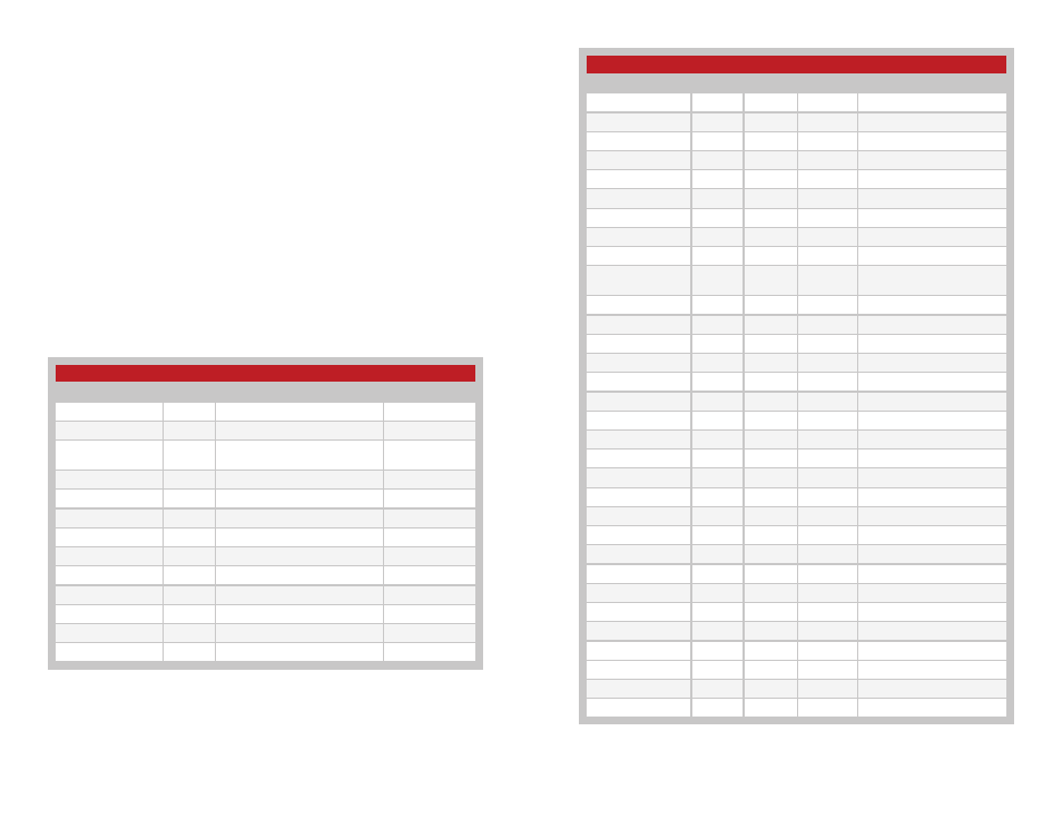
During normal operation, the volatile registers are used to control the
module. Figure 13 shows all of the configuration registers. Figure 12 shows
the default values for the non-volatile registers. These are what the module
uses when it powers up. Changing these values changes the module’s
default setting.
DTS Series Configuration Registers
Name
Address Location Operation Description
0x00
NV
R/W
Transmit channel setting
0x01
NV
R/W
Receive channel setting
0x02
NV
R/W
Operating mode settings
0x03
NV
R/W
UART data rate
0x04
NV
R/W
Network mode (Normal/Slave)
0x05
NV
R/W
Transmit wait timeout
0x06
NV
R/W
Network group ID
0x08
NV
R/W
Enable/disable CRC
0x09
NV
R/W
Minimum transmission unit
0x0A
NV
R/W
Enable/disable start-up
message
0x0B
NV
R/W
Enable/disable CSMA
0x0D
NV
R/W
Power state of module
0x0E
NV
R/W
Send ACK character on wake
0x22
NV
R
MAC address byte 5
0x23
NV
R
MAC address byte 4
0x24
NV
R
MAC address byte 3
0x25
NV
R
MAC address byte 2
0x26
NV
R
MAC address byte 1
0x27
NV
R
MAC address byte 0
0x78
NV
R
Firmware release number
0x4B
V
R/W
Transmit channel setting
0x4C
V
R/W
Receive channel setting
0x4D
V
R/W
Operating mode settings
0x4E
V
R/W
UART data rate
0x4F
V
R/W
Network mode (normal/slave)
0x50
V
R/W
Transmit wait timeout
0x51
V
R/W
Network group ID
0x53
V
R/W
Enable/disable CRC
0x54
V
R/W
Minimum transmission unit
0x56
V
R/W
Enable/disable CSMA
0x58
V
R/W
Power state of module
0x59
V
R/W
Send ACK character on wake
Figure 13: DTS Series Configuration Registers
Non-Volatile Register Default Values
Name
Address Description
Default Value
0x00
Transmit channel setting
16
0x01
Receive channel setting
16
0x02
Operating mode settings
+11dBm
DTS mode
0x03
UART data rate
2400bps
0x04
Network mode (Normal/Slave)
Normal
0x05
Transmit wait timeout
~16ms
0x06
Network group ID
0x00
0x08
Enable/disable CRC
Enabled
0x09
Minimum transmission unit
64 bytes
0x0A
Enable/disable start-up message
Enabled
0x0B
Enable/disable CSMA
Enabled
0x0D
Power state of module
Awake
0x0E
Send ACK character on wake
Yes
Figure 12: DTS Series Non-volatile Configuration Register Default Settings