Connection panels, Useful hints – Bang & Olufsen BeoSystem 3 Getting Started User Manual
Page 24
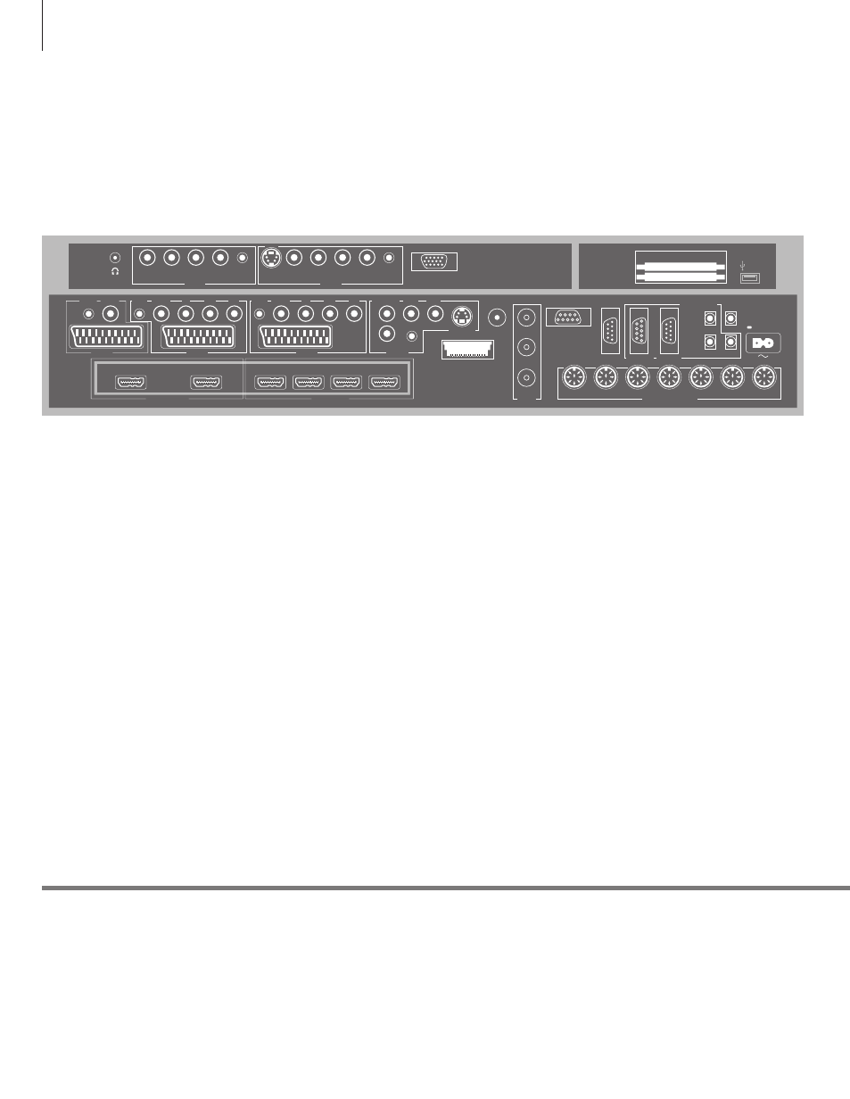
Connection panels
Any equipment you connect to the main connection panel must be registered in
the CONNECTIONS menu. Equipment connected to the side connection panel can
be registered in the CONNECTIONS menu.
Useful hints
Power saving
Mains cord
Master Link must not be connected if POWER SAVING is set to ON in the STANDBY SETTINGS menu.
If POWER SAVING is set to ON and the TV is in standby, the socket MASTERLINK is deactivated. This
means that you cannot access the TV from your link room audio or video system, while the main room
TV is in standby. Furthermore, it is not possible to make recordings on sources connected to any AV
sockets. See the Guide for further information.
Connect the ~ socket on the main connection panel of your TV to the wall outlet. The TV is in standby
mode and ready to be used.
AV1
Socket group for AV connection of a primary
recorder or set-top box. You can also connect
other types of extra video equipment.
AV2
Socket group for AV connection of additional
video equip ment.
AV3
Socket group for AV connection of additional
video equip ment.
The TV keeps a signal path open between a
recorder connected to the AV1 socket and a
recordable source connected to the AV3 socket.
This allows you to set the source on AV3 to switch
on automatically, as well as set a recorder on AV1
for timed recording of the source on AV3,
provided your connected equipment supports
these functions.
AV4
Socket group for AV connection of additional
video equip ment.
AV5
Socket group for AV connection of additional
video equip ment. You can also connect a
BeoMaster, a camera or a camcorder.
AV6
Socket group for AV connection of additional
video equip ment. You can also connect a camera
or a camcorder.
CTRL (AV1 – AV6)
For IR control signals to external equipment
connected to an AV socket.
L-IN, R-IN (AV4 – AV6)
Right and left line input. AV5 and AV6 is for audio
connection of, e.g., a camera or camcorder.
VIDEO IN (AV4 – AV6)
For video signal. On AV5 and AV6 you can
connect a camera or a camcorder.
Y – Pb – Pr (AV2 – AV3)
For video signals from an external source, e.g.
HDTV source. You can use the socket in
conjunction with an AV socket or a digital audio
socket.
SPDIF (AV1 – AV6)
Digital audio input socket, e.g. DVD player.
S VIDEO (AV4, AV6)
For the connection of equipment with Y/C output,
e.g., a game console.
HDMI OUT (DISPLAY 1 - 2)
Connect a plasma screen and/or a projector. If you
only connect a screen or a projector, connect it to
DISPLAY 1, otherwise connect the screen to
DISPLAY 1 and the projector to DISPLAY 2. You
cannot connect two screens or two projectors at
the same time.
HDMI IN (A–D)
For High Definition Multimedia Interface video
source or PC. An HDMI socket may be occupied
by built-in video equipment. The sources can be
registered to any of the AV socket groups. To
expand the number of HDMI sockets, connect an
HDMI Expander to the HDMI C socket.
ANT (1–3)
Aerial input socket DVB T/C (1) from external
aerial/cable TV network, DVB-S (2) from satellite
dish, external aerial/cable TV network (3) from
external aerial/analogue cable TV network.*
1
POWER LINK
CONTROL
CENTRE 1
CINEMA
MONITOR
SMARTCARD
PCMCIA
IR IN
DTV DATA
MASTER LINK
1(SUB)
1
ANALOGUE
DVB-S
DVB-T/C
2
3
2
3
4
TTL
5
6
ANT
HDMI IN
HDMI OUT
AV 4
AV 3
RS232
IR IN
CTRL
SPDIF
VIDEO IN
L IN
R IN
IR 1+2
LINK TV
S VIDEO
Y
SPDIF
CTRL
Pb
Pr
AV 2
AV 5
AV 1
Y
SPDIF
DISPLAY 1
CTRL
SPDIF
CTRL
Pb
Pr
R IN
L IN
VIDEO
IN
SPDIF
CTRL
DISPLAY 2
A
B
C
D
AV 6
R IN
L IN
VIDEO
IN
SPDIF
CTRL
VGA
S VIDEO
24