Chapter 3, Board layout – Lanner LEC-7106 User Manual
Page 14
14
Board Layout
Chapter 3
Embedded and Industrial Computing
PS/2 Keyboard Connector (KB1)
PS/2 Mouse Connector (MS1)
Serial-ATA Connector (SATA1/PSATA1): It is for
connecting a 2.5’’ harddisk to serve as your system’s
storage. It can support SATA II which features Data
transfer rates up to 3.0 Gb/s (300 MB/s). Note that PSATA1
has power on pin 7 to support eSATA connector.
4-pin Serial-ATA Power Connector (PW1): It is for
connecting the SATA power cord.
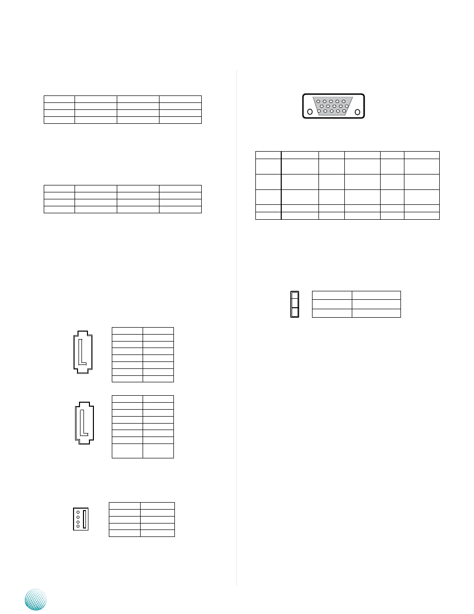
VGA (VGA1)
Pin
signal
Pin
signal
Pin
signal
1
Red Color
signal
6
GNd
11
N/A
2
Green Color
signal
7
GNd
12
ddC dAT
3
Blue Color
signal
8
GNd
13
HsYNC
4
N/A
9
VCC5
14
VsYNC
5
CRT_ON
10
GNd
15
ddC CLK
Clear CMOS jumper (CMOS1): It is for clearing the CMOS
settings.
Pin No.
Pin Name
1-2
Normal (default)
2-3
Clear CMOs
3
2
1
15 14 13 12 11
5 4 3 2 1
Pin No.
Function
1
GNd
2
TX0_P
3
TX0_N
4
GNd
5
RX0_N
6
RX0_P
7
GNd
Pin No.
Function
1
VCC12_Ps
2
GNd
3
GNd
4
VCC_Hdd
4
3
2
1
Pin No.
signal
Pin No.
signal
1
KdAT_R
2
N/A
3
GNd
4
VCC5_KB
5
KCLK_R
6
N/A
Pin No.
signal
Pin No.
signal
1
MdAT_R
2
N/A
3
GNd
4
VCC5_KB
5
MCLK_R
6
N/A
sATA1
1
2
3
4
5
6
7
PsATA1
1
2
3
4
5
6
7
Pin No.
Function
1
GNd
2
TX0_P
3
TX0_N
4
GNd
5
RX0_N
6
RX0_P
7
VCC5_
sATAdOM