Chapter 3, Board layout, Connectors and jumpers list – Lanner LEC-7106 User Manual
Page 12
12
Board Layout
Chapter 3
Embedded and Industrial Computing
Connectors and Jumpers List
The tables below list the function of each of the board
jumpers and connectors by labels shown in the above
section. The next section in this chapter gives pin
definitions and instructions on setting jumpers.
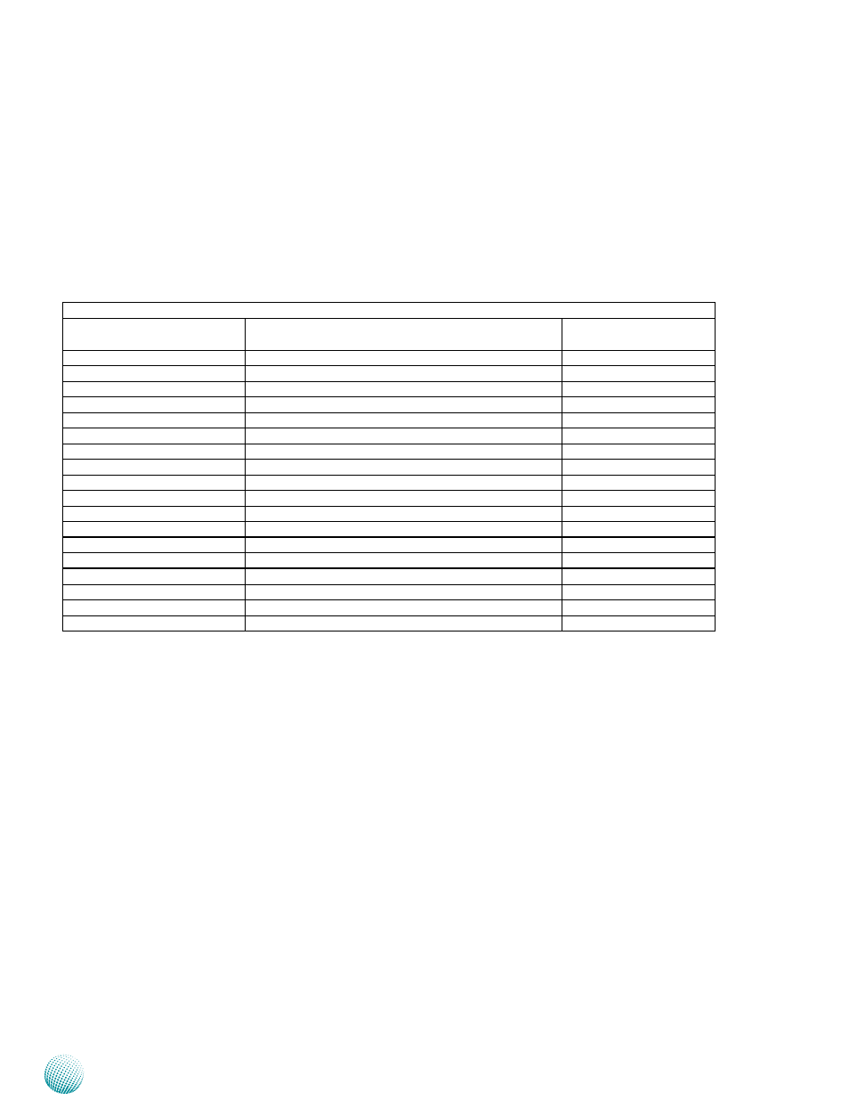
Table 3.1 Connector List for the Main Board
Labels
Function
Pin Definition Reference
Page
COM1~COM4
RS-232 COM Ports
P13
CMOS1
Clear CMOS Jumper
P14
CN9
SIM Card Reader
P15
J12
Power Switch with Phoenix Contact Connector
P15
JSPI1
Serial Peripheral Interface
Reserved for factory use
KB1
Keyboard/Mouse Connector
P14
LIN1
Line-Out Audio Jack
P13
LPC1
Low-pin Cound Connector
Reserved for factory use
MIC1
Mic-in Audio Jack
P13
MPCIE1
Mini-PCIe Connector
P15
MS1
PS/2 Mouse Connector
P14
PW1
SATA Power
P14
RST1
Reset Button
P15
SATA1/PSATA1
Serial-ATA Connector
P14
SC1T1/SC2T1/SC3T1/SC4T1
COM1/COM2/COM3/COM4 Pin 9 Function Selection
P13
USB1/USB2
Dual USB Ports
P15
USB3
USB Pin Header
P15
VGA1
VGA Connector
P14