Chapter 2, System components, Front components – Lanner LEC-2530 User Manual
Page 8
8
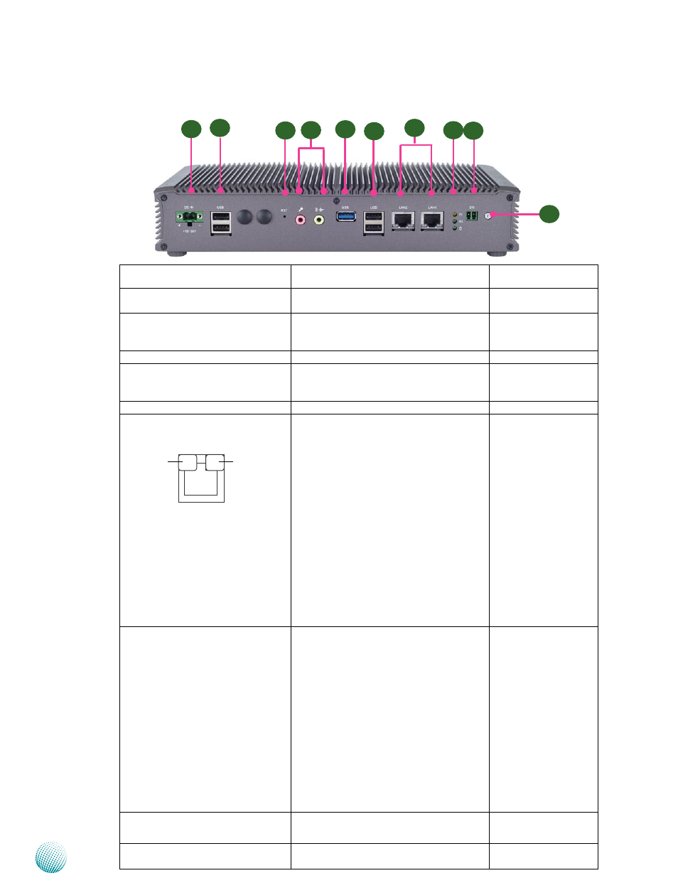
System Components
Chapter 2
Embedded and Industrial Computing
Component
Description
Pin Definition
Reference
F1 Power-in Connector
A phoenix connector for DC-in power supply;
the system requires a 9~30V power input.
DCIN1 on page 17
F2
Four USB 2.0 Ports
Four USB 2.0 type A connector.
USB1 of LEK-IOA10 on
page 17/ USB1 of LEB-
2530 on page 15
F3 Reset
Reset switch
F4 MIC IN/LINE OUT
Connect audio devices to these ports. The
microphone and line out port are provided by
Realtek ALC
886 HD Audio.
F5 USB 3.0 Port
An USB 3.0 type A connector.
USB2 on page 15
F6 Two 10/100/1000Mbps LAN ports
Two RJ-45 (network) jacks with LED indicators as
described below. Both LAN ports are provided
by Intel I210. The I210 supports PXE and iSCSI
remote boot options.
LINK/ACT (Yellow)
On/Flashing: The port is linking and active
•
in data transmission.
Off: The port is not linking.
•
SPEED (Green/Yellow)
Yellow: The connection speed is
•
1000Mbps.
Green: The connection speed is 100Mbps
•
Off: The connection speed is 10Mbps.
•
LAN1/LAN2 on page
15
F7 HDD (Yellow)
3G Status (Green) and
Power LED (Green)
HDD
Blinking: data access activities
•
Off: no data access activities
•
3G Status
Blinking: 3G transmission activities
•
On: 3G expansion card exists
•
Off: no 3G expansion card exists
•
Power
On: The computer is on.
•
Off: The computer is off .
•
F8 Power-on Switch
A power-on switch through the Phoenix
contact for remote power-on/off control
PSBTN2 on page 16
F9 Power Button with dual LED
ATX Power-on button with LEDs: Standby
mode in Red; Power-on mode in Green
Front Components
sPEEd
LINK/ACT
F3
F1
F7
F9
F5
F8
F2
F4
F6
F2