Chapter 3, Board layout – Lanner LEC-2530 User Manual
Page 17
17
Board Layout
Chapter 3
Embedded and Industrial Computing
LEK-IOA10 Pin Definitions
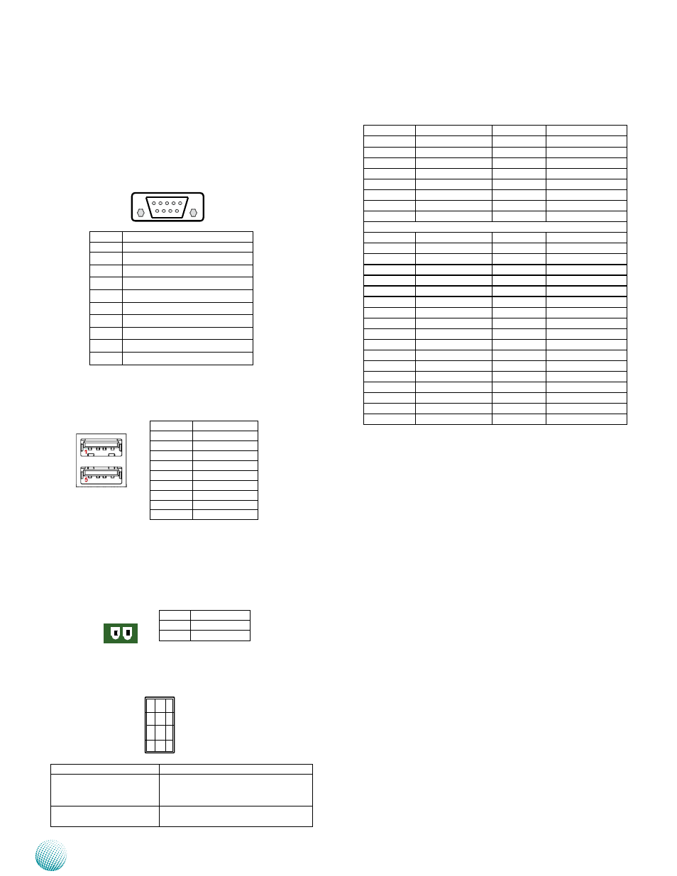
RS-232 Serial Port (COM3 and COM4): It is an RS-232
serial port through a D-SUB9 connector.
Dual USB 2.0 Port (USB1):
DC_IN CONNECTOR (DCIN1): A Phoenix connector for
external power supply.
USB Signal Selection (USB_SEL1)
Pin No.
signal
Rs-232
1
data Carrier detect ( dCd # )
2
Receive data ( RXd )
3
Transmit data ( TXd )
4
data Terminal Ready ( dTR # )
5
Ground ( GNd )
6
data set Ready ( dsR # )
7
Request To send ( RTs # )
8
Clear To send ( CTs # )
9
Ring Indicator ( RI # )
6 7 8 9
1 2 3 4 5
Pin No.
signal
1
+5V
2
dATA-
3
dATA+
4
GNd
5
ssRX-
6
ssRX+
7
GNd
8
ssTX-
9
ssTX+
Pin No.
Pin Name
1
GNd
2
dC_VIN
1 2
9
10
11
12
1
2
3
4
Pin No.
Pin Name
1-5,2-6,3-7,4-8 (default) For use with the LEB-7230 board only;
the MPCIE1 connector supports both
PCIe and UsB signals.
5-9,6-10,7-11,8-12
For other uses; the MPCIE1connector
supports PCIe signal only
Mini PCI Express Connector (for cards with PCI Ex-
press 1X and USB 2.0 signals, MPCIE1):
PIN
signal
PIN
signal
1
WAKE#
2
+3.3Vaux
3
COEX1
4
GNd
5
COEX2
6
+1.5V
7
CLKREQ#
8
UIM_PWR
9
GNd
10
UIM_dATA
11
REFCLK-
12
UIM_CLK
13
REFCLK+
14
UIM_REsET
15
GNd
16
UIM_VPP
Key
17
RsVd
18
GNd
19
RsVd
20
W_dIsABLE#
21
GNd
22
PERsT#
23
PERn0
24
+3.3Vaux
25
PERp0
26
GNd
27
GNd
28
+1.5V
29
GNd
30
sMB_CLK
31
PETn0
32
sMB_dATA
33
PETp0
34
GNd
35
GNd
36
UsB_d-
37
GNd
38
UsB_d+
39
+3.3Vaux
40
GNd
41
+3.3Vaux
42
LEd_WWAN#
43
GNd
44
LEd_WLAN#
45
RsVd
46
LEd_WPAN#
47
RsVd
48
+1.5V
49
RsVd
50
GNd
51
RsVd
52
+3.3Vaux