Chapter 3, Board layout, Connectors and jumpers list – Lanner VES-8X2 User Manual
Page 10
10
Board Layout
Chapter 3
Embedded and Industrial Computing
Connectors and Jumpers List
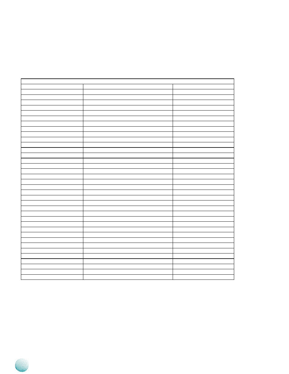
The tables below list the function of each of the board
jumpers and connectors by labels shown in the above
section. The next section in this chapter gives pin
definitions and instructions on setting jumpers.
Table 3.1 Connector List for VES-8X2
Labels
Function
Pin Definition Reference Page
JP2
COM1 pin 9 signal select
P12
JP3
COM2 pin 9 signal select
P12
JP4
COM2 RS-232/422/485 select
P12
JP5
Clear CMOS
P14
ATX1
ATX Power connector
P11
ATX2
ATX Power connector
P11
C_FAN1
CPU fan connector
P13
CN1
USB connector 2&3
CN2
Audio input connector
CN3
USB connector 0&1
CN4
SPDIF connector
P12
CN5
CD-ROM audio input connector
P12
CN6
Floppy connector
P14
JBKL1
LCD inverter connector
P14
JBKL2
LCD inverter connector
P14
JCD1
CD-ROM audio input connector
P14
JCOM1
Serial Port 2 in RS-232 mode
JDIO1
General purpose I/O connector
P11
JFP1
Miscellaneous setting connector
P14
JIR1
IrDA connector
P12
JLVDS1
LVDS connector
P13
JTV1
TV out connector
P13
JRS422/1
Serial Port 2 in RS422/485 mode
P11
JUSB1
USB connector 7
P13
JUSB2
USB connector 4 and 5
P13
KB_MS1
PS/2 keyboard & PS/2 mouse connector
PCI1
PCI slot 1
PCIE_1
PCI Express x1 connector
PCIE_2
PCI Express x1 connector
PCIE_3
PCI Express x16 connector
PEC1
PCI Express card
POWER_ON1
Power on button
RESET1
Reset button
S_FAN1
System fan connector 1
P13
S_FAN2
System fan connector 2
P13
SATA1/2/3/4
Serial ATA connector 1/2/3/4