Chapter 3, Motherboard information – Lanner MR-330A User Manual
Page 13
11
Motherboard Information
Chapter 3
Network Application Platforms
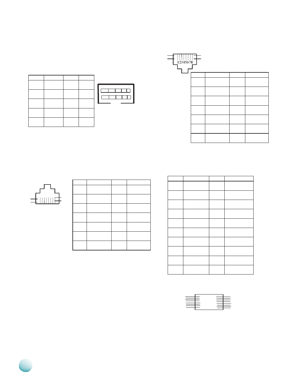
Ethernet 0/1Copper Connector (RJ1)
Ethernet 0/1Fiber Connector(CN1)
Serial Interface Connectors(JP6): It is for connecting
the RS-232 serial port module cable. And the port is
assigned as COM1.
Ethernet Switch Ethernet 0 (P5): The Ethernet switch of
4 Gigabit ports is provided by the Marvell Linkstreet
88E6161 PHY through RGMII.
Ethernet 1 and Ethernet 2 Port : These two Gbe RJ45
and SFP combo Small Form-factor Pluggable (SFP)
ports are provided by the Marvell 88E1111 GbE PHY
It has the following capability highlights:
Compliant with the IEEE 802.3 10Base-T/100Base-
•
Tx/ 1000Base-T
Auto-adjusting between 10M/100M/1000M
•
connection speed
Auto-negotiation between MDI and MDIX
•
crossover at all speeds of operation
Energy Detect and Energy Detect+ low power
•
modes
Three loopback modes for diagnostics
•
Software programmable LED modes including
•
LED testing
PIN NO. Function PIN NO. Function
1
VCC3
6
N.C.
2
RXD1
7
N.C.
N
TXD1
8
N.C.
4
NC
9
N.C.
5
GND
10
N.C
1 2 3 4 5
6 7 8 9 1 0
PIN NO.
Function
PIN NO.
Function
T1
GND
T11
GND
T2
VCC3
T12
S_IN-
T3
GND
T13
S_IN+
T4
NC
T14
GND
T5
NC
T15
SFP11_VCCR
T6
VCC3
T16
SFP11_VCCT
T7
NC
T17
GND
T8
SFPA_LOS10
T18
S_OUT+
T9
GND
T19
S_OUT-
T10
GND
T20
GND
PIN NO.
Function
PIN NO.
Function
1
P0_MDIP0
6
1 . 8 V _ G E _
PORT
2
P0_MDIN0
7
P0_MDIP2
3
P0_MDIP1
8
P0_MDIN2
4
P0_MDIN1
9
P0_MDIP3
5
1 . 8 V _ G E _
PORT
10
P0_MDIN3
LED1 Port1_100M_
GREEN-2
LED2
Port_1000M_
AMBER-2
LED3 P o r t _ L i n k /
ACT-2
LED4
VCC3
LED1
LED2
LED3
LED4
PIN NO.
Function
PIN NO.
Function
1
P1_MDXP0
6
P1_MDXN1
2
P1_MDXN0
7
P1_MDXP3
3
P1_MDXP1
8
P1_MDXN3
4
P1_MDXP2
9
5
P1_MDXN2
10
LED1 Port1_100M_
GREEN-2
LED2
Port_1000M_
AMBER-2
LED3 P o r t 1 _ L i n k /
Act-2
LED4
VCC3
1
2
.
10
20
19
.
11
LED1
LED2
LED3
LED4