Chapter 3, Motherboard information – Lanner MR-330A User Manual
Page 12
10
Motherboard Information
Chapter 3
Network Application Platforms
NetRom Connector(JP3): The Net ROM device is the
tool for simulating the boot image during project
developing stage. The NetROM eliminates the need to
burn EPROMs or flash to debug code by utilizing the
Ethernet to download the code images
CompactFlash Connector (P1): It is for connecting a
Compact Flash card to be served as your system’s
storage. The connector is a CF Type II slot which could
fit both CF Type I or CF Type II cards.
1 2 3 4 5 6 7 8 9 1 0 1 1 1 2 1 3 1 4 1 5 1 6
32 31 30 29 28 27 26 25 24 23 22 21 20 19 18 17
Pin No.
Function
Pin No.
Function
1
NET_A19
2
NET_A16
3
NET_A15
4
NET_A12
5
NET_A7
6
NET_A6
7
NET_A5
8
NET_A4
9
NET_A3
10
NET_A2
11
NET_A1
12
NET_A0
13
NET_D0
14
NET_D1
15
NET_D2
16
GND
17
NET_D3
18
NET_D4
19
NET_D5
20
NET_D6
21
NET_D7
22
NET_CE#
23
NET_A10
24
BOOT_OE#
25
NET_A11
26
NET_A9
27
NET_A8
28
NET_A13
29
NET_A14
30
NET_A17
31
NET_A18
32
5V
Bootloader Mode Jumper (JP5): There are two bootloader
modes on the MR-330 board; namely, failsafe and
normal bootloader mode. Use this jumper to switch
between them.
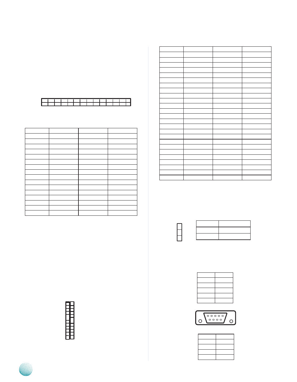
External Serial Port(P3):
It is the RS-232 serial port and
assigned as COM0.
Pin No.
Function
Pin No.
Function
1
Ground
2
Data 3
3
Data 4
4
Data 5
5
Data 6
6
Data 7
7
CS1#
8
N.C.
9
Ground
10
N.C.
11
N.C.
12
N.C.
13
+5V
14
N.C.
15
N.C.
16
N.C.
17
N.C.
18
Addr 2
19
Addr 1
20
Addr 0
21
Data 0
22
Data 1
23
Data 2
24
N.C.
25
N.C.
26
N.C.
27
Data 11
28
Data 12
29
Data 13
30
Data 14
31
Data 15
32
CS3#
33
N.C.
34
IOR#
35
IOW#
36
+5V
37
IRQ 15
38
+5V
39
N.C.
40
N.C.
41
Reset#
42
IOCHRDY
43
DMA REQ#
44
DMA ACK#
45
CF Active
46
PDIAG#
47
Data 8
48
Data 9
49
Data 10
50
Ground
1
2
3
Pin No.
Function
Short 1-2
Failsafe
Short 2-3
Normal
Pin No.
Pin name
1
N.C.
2
SIN0
3
SOUT0
4
N.C.
5
GROUND
Pin No.
Pin name
6
N.C.
7
N.C
8
N.C.
9
N.C.
6 7 8 9
1 2 3 4 5
25
24
.
.
.
.
.
1
50
.
.
.
.
.
26