Chapter 1, Introduction, Front panel features – Lanner FW-8895 User Manual
Page 7
3
Introduction
Chapter 1
Network Application Platforms
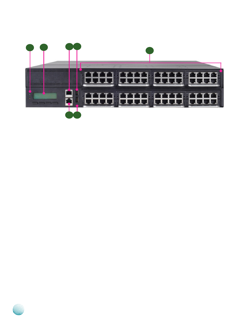
F1 Power/Status/HDD LED
Power: If the LED is on it indicates that the system is powered on. If it is off, it indicates that the system is powered off.
Status: This LED is programmable. You could program it to display the operating status with the behavior like:
If the LED is green, it indicates that the system’s operational state is normal. If it is red, it indicates that the system is
malfunctioning.
HDD:
If the LED blinks, it indicates data access activities; otherwise, it remains off.
F2 System Panel: LCD System Panel
The LCD System Panel can be programmed to display operating status and configuration information. For more details
or sample programming code, please refer to the Drivers and user’s manual CD.
F3 Management Port
This FastEthernet port can be connected for configuration or troubleshooting purpose. A conformity with IPMI (Intelligent
Platform Management Interface) can be implemented through OPMA on this interface.
F4 Console Port
By using suitable rollover cable or RJ-45 to DB-9 Female (Cisco console cable), you can connect to a computer terminal
for diagnostic or configuration purpose. Terminal Configuration Parameters: 115200 baud, 8 data bits, no parity, 1 stop
bit , no flow control.
F5 Reset Switch
The reset switch can be used to reboot the system without turning off the power.
F6 Two USB 2.0 Ports
It connects to any USB devices, for example, a flash drive.
F7 Swappable Ethernet Modules (with LAN bypass model options)
LINK/ACT (Yellow)
•
On/Flashing: The port is linking and active in data transmission.
•
Off: The port is not linking.
SPEED (Green/Amber)
•
Amber: The connection speed is 1000Mbps.
•
Green: The connection speed is 100Mbps
•
Off: .The connection speed is 10Mbps.
Front Panel Features
F3
F4
F5
F1
F7
F2
F6