Chapter 3, Motherboard information, Jumper settings – Lanner FW-8895 User Manual
Page 17
13
Motherboard Information
Chapter 3
Network Application Platforms
Jumper Settings
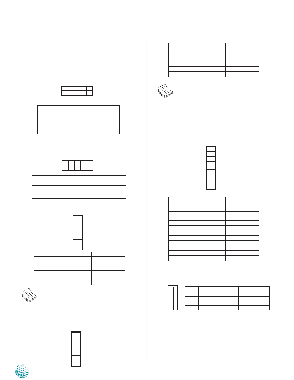
LCM_1: USB-type front LCD Message Display Module
(LCM). It supports both text and graphic type of LCM. The
board also facilitates Parallel -type LCM connector, refer to
jumper J23.
LCM_2: USB-type front LCD Message Display Module
(LCM). This connector is reserved for customization
purpose.
MGT1: RJ 45 management port connector
Note: Unlike the other management port
connector (MGT2), it doesn’t share an output port
(the Management port on the front panel) with
the IPMI signal Hence, no switch is required to
switch between these two signals.
MGT2: RJ 45 management port connector
Pin No.
Function
Pin No.
Function
1
P5V_SB
2
P5V
3
USB_PCH_P5N
4
5
USB_PCH_P5P
6
HDD_LED_N
7
GND
8
GND
9
NTXD2
10
NRXD2
9 1
10 2
Pin No.
Function
Pin No.
Function
1
MGT2_MDIP_0
2
MGT2_MDIN_0
3
MGT2_MDIP_1
4
MGT2_MDIN_1
5
MGT2_MDIP_2
6
MGT2_MDIN_2
7
MGT2_MDIP_3
8
MGT2_MDIN_3
9
MGT_LAN2_100#
10
MGT_LAN2_ACT#
11
MGT_LAN2_1G#
12
P3V3_AUX
1
3
5
7
9
11
2
4
6
8
10
12
12
10
8
6
4
2
11
9
7
5
3
1
Note: This MGT2 signal will not pass through
when the IPMI card is present (board reference NO.
OPMA1); The management port and IPMI share
the same output port (the Management port on
the front panel). Use the jumper OPEN2 to switch
between these two signals.
ATX5: 24-Pin ATX Power Connector
ATX1, ATX3: 8-Pin ATX Power Connector
SATA1: SATA Revision III Drive Connector
SATA2~SATA4: SATA Revision II Drive Connector
It is for connecting a 3.5’’ SATA harddisk to be served
as your system’s storage. The system can support up to
4 3.5" disks in maximum. The system’s BIOS supports
Pin No.
Function
Pin No.
Function
1
+3.3V
2
+3.3V
3
+3.3V
4
-12V
5
Ground
6
Ground
7
+5V
8
PSON-
9
Ground
10
Ground
11
+5V
12
Ground
13
Ground
14
Ground
15
Power Good
16
NC
17
Stand-By 5V
18
+5V
19
+12V
20
+5V
21
+12V
22
+5V
23
3.3V
24
GND
1
3
5
7
2
4
6
8
Pin No.
Function
Pin No.
Function
1
GND
2
12V
3
GND
4
12V
5
GND
6
12V
7
GND
8
12V
23
21
19
1
24
23
20
2
2 10
1 9
Pin No.
Function
Pin No.
Function
1
P5V_SB
2
USB_PCH_P4N
3
USB_PCH_P4P
4
GND
5
PWR_LED-
6
FAULT_N
7
HDD_LED_N
8
PWRON_N
9
P3V3_AUX
10
PCH_PLTRST_LCM_N
Pin No.
Function
Pin No.
Function
1
MGT2_MDIP_0
2
MGT_MDIN_0
3
MGT2_MDIP_1
4
MGT_MDIN_1
5
MGT2_MDIP_2
6
MGT_MDIN_2
7
MGT2_MDIP_3
8
MGT_MDIN_3
9
MGT_LAN_100#
10
MGT_LAN_ACT#
11
MGT_LAN_1G#
12
P3V3_AUX