Djustments – Jordan Valve 667M Series Diaphragm Actuator User Manual
Page 2
667M S
erieS
D
iaphragM
a
ctuator
-2-
Loading Connection cont’d
5.
If the valve stem travel or pressure range is in
correct, refer to the “Adjustments” section of this
manual.
Do not place the valve in service if it is not responding
properly to diaphragm loading pressure changes.
For ease of service, ensure that the control valve is locat-
ed for easy access and serviceability with room above
for accessibility. Ensure that sufficient room is provided
below should removal of the actuator and valve plug be
necessary.
a
djustments
Travel
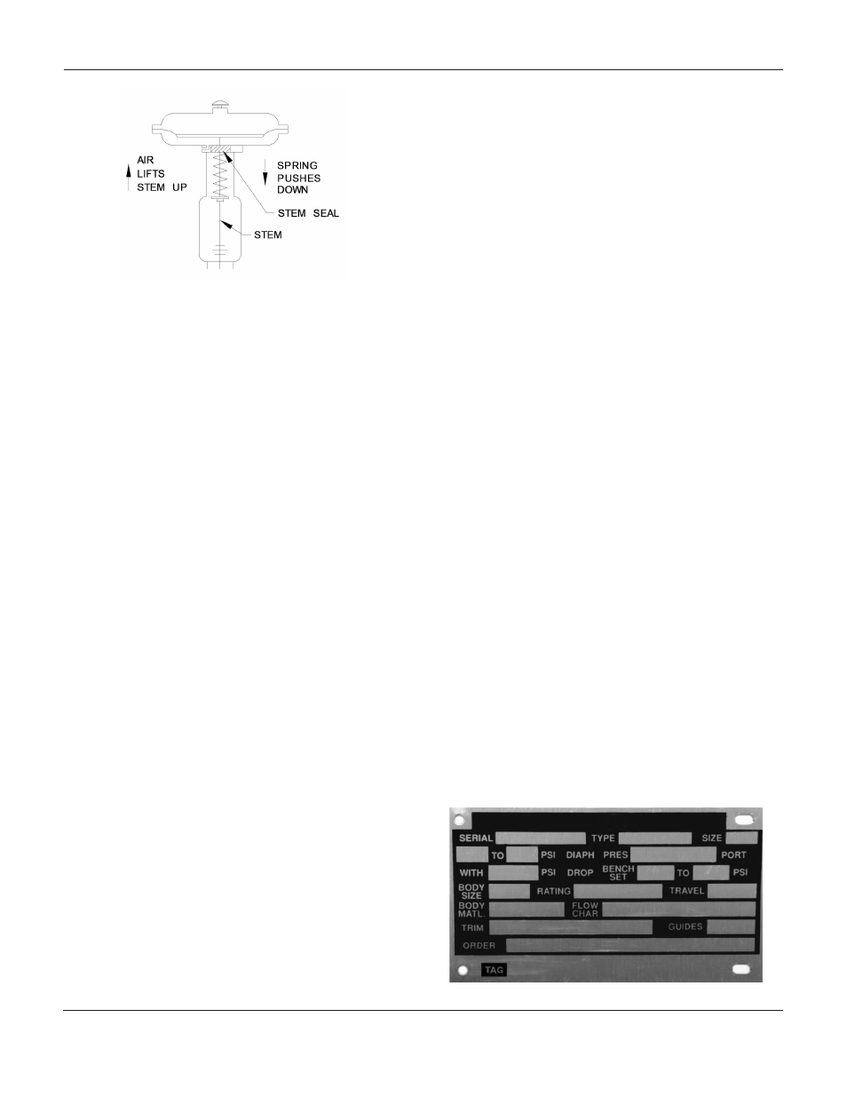
Refer to the nameplate on the yoke of the actuator for
details on the specific construction and operating range
of the control valve assembly.
The requirements of your specific application will dictate
the spring and diaphragm used in your 667M Actua-
tor, and when in service, the actuator should create full
travel of the valve plug when diaphragm pressure is
applied according to the range indicated on the name
plate. Generally, the diaphragm pressure range is 3 to
15 PSI or 6 to 30 PSI, but other ranges may be used.
If the motion during the actuator travel differs from the
travel stamped on the actuator nameplate, adjust ac-
cording to the following directions. In order to adjust
the travel of a direct-acting valve, slightly pressure the
actuator to move the valve plug off of the seat. This
reduces the chance of damaging the valve plug or seat
during adjustments.
1.
Loosen and back off the stem locknuts and
indicator disc from the stem connector.
2.
Loosen the stem connector cap screws.
Note: Do not use wrenches or other tools directly on
the valve stem as this could cause damage to the
stem surface and valve packing.
3.
Tighten the locknuts (Keys 14 and 20) and
complete the adjustment by either screwing the
valve stem into the stem connector to lengthen
travel or out of the stem
connector to shorten travel.
4.
Cycle the actuator to ensure that the correct
travel has been achieved and repeat the
adjustment if necessary.
5.
When the correct travel has been reached
tighten the stem connector cap screws.
6.
Raise the travel indicator disc by threading the
stem locknuts against the stem connector.
7.
Adjust the travel scale to match the disc.
Spring
If the loading pressure range applied to reach the de-
sired travel differs from that specified on the nameplate,
a spring adjustment is required.
Check the “Bench Set” pressure range on the nameplate
when the valve contains no pressure and the packing is
loosely inserted in the bonnet. Refer to the “Diaphragm
Pressure” range on the nameplate when the valve is
controlling the specified pressure drop and the packing
is tightened to stop leaks around the stem.
1.
Monitor the loading pressure while making
adjustments. Be sure not to exceed the
pressure specifications of either
the loading regulator or the actuator casings.
2.
Each actuator spring has a fixed pressure span.
Changing the spring compression shifts the
span up or down to make the valve
travel coincide with the loading pressure range.
Figure 1: Schematic of 667M Actuator
Figure 2: Nameplate on the 667M Actuator