Maintenance, Valve seats, Stem & disc pin replacement – Jordan Valve Mark 33 Series – Boiler Feedwater Control Valve User Manual
Page 2: Packing
Maintenance
Caution: Make certain that there is no pressure in the valve
before loosening any fittings or joints. The following steps
are recommended:
1.
Close inlet shutoff valve.
2.
Allow pressure to bleed off through downstream piping.
Do not attempt to reverse the flow through the valve by
bleeding pressure from the upstream side of the valve.
3.
When the pressure gauges indicate that all pressure has
been removed from the system, close the outlet shutoff
valve, and the valve may be serviced.
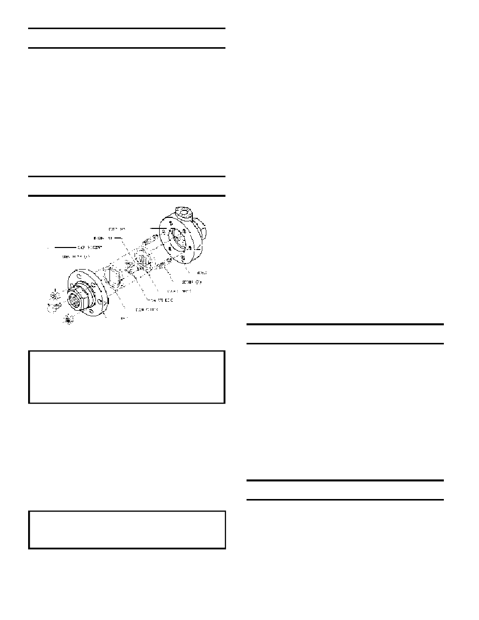
Note: refer to the drawing at the end of this document for
description and proper orientation of parts.
Valve Seats
A. Disassembly
The seats of Jordan valves are precision-lapped. Main-
taining such tolerances is of paramount importance for
your assurance of excellent control and tight shutoff. Do
not use metallic objects in removing the seats. Care in
handling is imperative.
1.
Close the shutoff valve on each side of the control valve,
and remove the valve from line.
2.
Note scribed “<“ on the side of the valve body and cap.
Secure the body outlet flats in a vise. Remove the cap
bolts and two nuts, and lift the cap straight up.
3.
Before removing, check the valve disc for a stamped
arrow. This arrow points to the “<“ on the body. Remove
the disc guide and the valve disc. Place the valve disc on
the bench with lapped surface facing up. Protect the
lapped surfaces on both sides of the disc guide.
It is imperative that the disc pin is not rotated when
disassembling, cleaning or reassembling, since this
affects the stroke adjustment of the valve.
4.
Lightly tap on the body to remove the valve plate. Invert
the body, let valve plate drop out into your hand, and
place it on the bench with lapped surface facing up.
5.
Clean all the parts, body, and cap with solvent. Place a
piece of 4/0 polishing cloth or jewelers cloth on a smooth,
flat surface such as surface plate, and polish the lapped
seating surfaces of the disc, plate, and disc guide using a
“figure 8” motion. If the parts are scarred, do not attempt to
relap them, but return them to the factory for repair or
replacement. If the seats are not scarred deeply, they can
be repaired at nominal cost.
6.
The vertical sections of the disc guide serve as guides for
the valve disc while stroking. A 0.005 feeler gauge
should be used to check for clearance between this
surface and the side of the valve disc. If the clearance is
less, clean the guide surfaces in the disc guide with a fine
file.
B. Reassembly
1.
Place the valve plate in the body, lapped surface facing
the cap. The index pin hole should be on the same side
as the “<“ on the body. Align the disc pin so that it is
centered in the body bore and protrudes through the
center slot in the valve plate.
2.
Place the valve disc on the valve plate, engaging the disc
pin. The arrow on the disc should point to the “<“ on the
body.
3.
Place the disc guide onto the valve plate, engaging the
index pin. Rotate the assembly slightly until the slot
openings in the valve disc are parallel to the openings in
the valve plate, and perpendicular to the valve stem.
Stroking the valve will aide in this alignment.
4.
Align the “>“ on the cap with the “<“ on the body, and
place the cap over the two studs in the body.
5.
Install the nuts and cap bolts. Tighten uniformly. See
torque requirements and tightening procedures.
Stem & Disc Pin Replacement
1.
Remove the valve disc and the valve plate, following the
procedure outlined under VALVE SEATS.
2.
Loosen the stem connector nut and bolt and remove
connector assembly.
3.
Back out the four allen head screws which will allow the
valve body to be separated from the valve yoke.
4.
Loosen the stem locknut and rotate the disc pin counter-
clockwise, pulling the valve stem upward while doing so.
Do not remove the valve stem completely but raise it
sufficiently so that the disc pin may be removed by pulling
up and out.
5.
Replace the disc pin and reassemble in reverse order
following the procedures outlined under VALVE SEATS
and STROKE ADJUSTMENT.
Packing
1.
Remove connector assembly.
2.
Remove both packing flange nuts.
3.
Remove packing flange and packing follower.
4.
Remove packing retainer and the packing spring.
5.
Clean the packing bore with solvent and blow out
thoroughly.
6.
Assemble in reverse order and tighten the packing nut so
that the packing follower bottoms out on top of the valve
body.