Jordan Valve Mark ED & ET Series Globe Style Control Valve (1-6) User Manual
Page 2
M
ark
ED
anD
ET S
EriES
E 1-6
inch
G
lobE
S
TylE
c
onTrol
V
alVES
-2-
Disassembly Continued,
5.
Remove the cage and gaskets from the valve
body. With restricted trim, (figure 10) remove
the seat ring adaptor (key 5) and the cage
adaptor (key 4).
6.
Remove the seat ring and its gasket. With
composition seats, remove the disc retainer,
disc seat and TFE disc.
Reassembly
Except where indicated refer to Figure 1 for part descrip-
tions used in the following procedure.
1.
Clean all gasket-seating surfaces. Use new gas
kets only for reassembly.
2.
With restricted trim (figure 10) install the seat
ring adaptor gasket (key 13) and the adaptor
(key 5).
Figure 2: Equal Percentage Cage
3.
Replace the seat ring gasket (key 12) and install
the seat ring (key 8). If using a composition seat,
assemble it by placing the TFE disc (key 20) into
the disc retainer (key 18), then sliding this as-
sembly over the disc seat (key 19).
4.
Place the cage (key 3) onto the seat ring (key
9). Any rotational orientation of the cage
with respect to the valve body is acceptable.
5.
With full-sized trim, install cage gasket (key 10),
spiral wound gasket (key 11) and bonnet gasket
(key 9) onto the cage shoulder.
6.
With restricted trim, install the cage gasket (key
10), spiral wound gasket (key 11) and an ad-
ditional cage gasket (key 10) onto the
cage shoulder. Install the cage adaptor
and place the bonnet gasket onto the adaptor.
7.
If installing a new stem in the valve plug, screw
the new stem into the valve plug. Refer
to Table 2 for appropriate torque values and drill
sizes. Drill through the stem, using the hole in
the valve plug as a guide. Remove any
chips or burrs and drive in a new groove
pin to lock the assembly.
8.
If the seal ring appears damaged, remove and
replace with a new one. Be careful not to scratch
the ring groove surfaces. Damage to the ring
groove surface may prevent the
new ring from sealing properly. The seal
ring must either be pried or cut from the
groove and therefore cannot be reused.
If possible, lapping of metal seats should be
done before seal ring installation. Refer
to the “Lapping Metal Seats” procedure
in this manual.
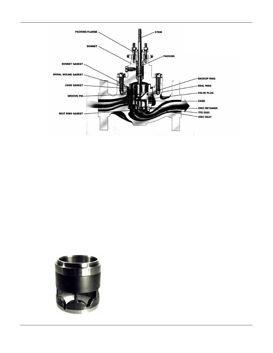
Figure 1:
Sectional View of A-100
Series Valve Body with
Full Size Trim