Thermal system, Valve stroke adjustment, Ordering spare parts – Jordan Valve Mark 85 Series - Controlled Failure Temperature Regulator User Manual
Page 4: Torque values
Thermal System
The Series 85 thermal system consists of the sens-
1.
ing bulb, capillary, armor, diaphragm dome, dia-
phragm case, diaphragm plate, optimal pressure
gauge, and Tru-Seal. This complete unit contains
the thermostatic charge. DO NOT TAMPER WITH
THE UNIT OR LOOSEN PRESSURE GAUGE BE-
CAUSE THE THERMOSTATIC CHARGE COULD BE
LOST. If the thermostatic charge is lost, the thermal
system must be replaced as a complete unit. It can-
not be repaired in the field. It must be returned to
the factory for repairs.
The complete thermal system is easily replaced in
2.
the field by removing the stem connector assembly
(9Y, 10Y, 11Y) and by then removing the four fillister
head screws (7Y).
Replace the thermal system in the reverse order.
3.
CHECK THE STROKE ADJUSTMENT AS OUTLINED
BELOW.
Valve Stroke Adjustment
A. DIRECT ACTING
With the thermal system attached to the yoke and
1.
the stem connector assembly secured, release the
spring compression by rotating the adjusting wheel
(5Y) downward. The sensing bulb should be main-
tained at a temperature below the low point of the
regulator range. This ensures that the thermal sys-
tem is stroked fully upward.
Remove the cap (2V) and check the alignment
2.
of the orifices in the disc and plate. The disc (4V)
should be in the uppermost position with the ori-
fices perfectly aligned and fully open.
Adjust the position of the disc (4V) on the plate
3.
(3V) by first loosening the stem connector nut and
bolt (10Y, 11Y) and locknut (4Y) and then threading
the actuator stem (8Y) into the adjusting screw (3Y)
to raise the disc, or out of the adjusting screw to
lower disc.
When the proper adjustment is obtained, tighten
4.
the stem connector nut (11Y) and bolt (10Y) and
the locknut (4Y).
Replace the cap (2V) as outlined under VALVE
5.
SEATS.
B. REVERSE ACTING
With the thermal systems attached to the yoke,
1.
and with the stem connector assembly secure,
fully compress the spring by rotating the adjusting
wheel (5Y) upward. This ensures that the thermal
system is stroked fully downward.
Remove the cap (2V) and check the alignment
2.
of the orifices in the disc and plate. The disc (4V)
should be in the lower-most position with the
orifices perfectly aligned and fully open.
If the disc and plate are not properly aligned, follow
3.
steps 3, 4, and 5 as outlined above for DIRECT ACT-
ING STROKE ADJUSTMENT.
Ordering Spare Parts
Use only genuine Jordan Valve parts to keep your valve
in good working order. So that we can supply the parts,
which were designed for your valve, we must know ex-
actly which product you are using. The only guarantee to
getting the correct replacement parts is to provide your
Jordan Representative with the valve serial number. This
number is located on the valve identification tag. If the
serial number is not available, the parts needed for your
valve might be determined using the following informa-
tion: Model Number, Valve Body Size, Seat Material and
Cv Rating, Spring Range and Set Point, Trim Material, Part
Name - Number and Quantity.
NOTE: Any parts ordered without a valve serial number
that are found to be incorrect are subject to up to a mini-
mum 25% restock charge when returned.
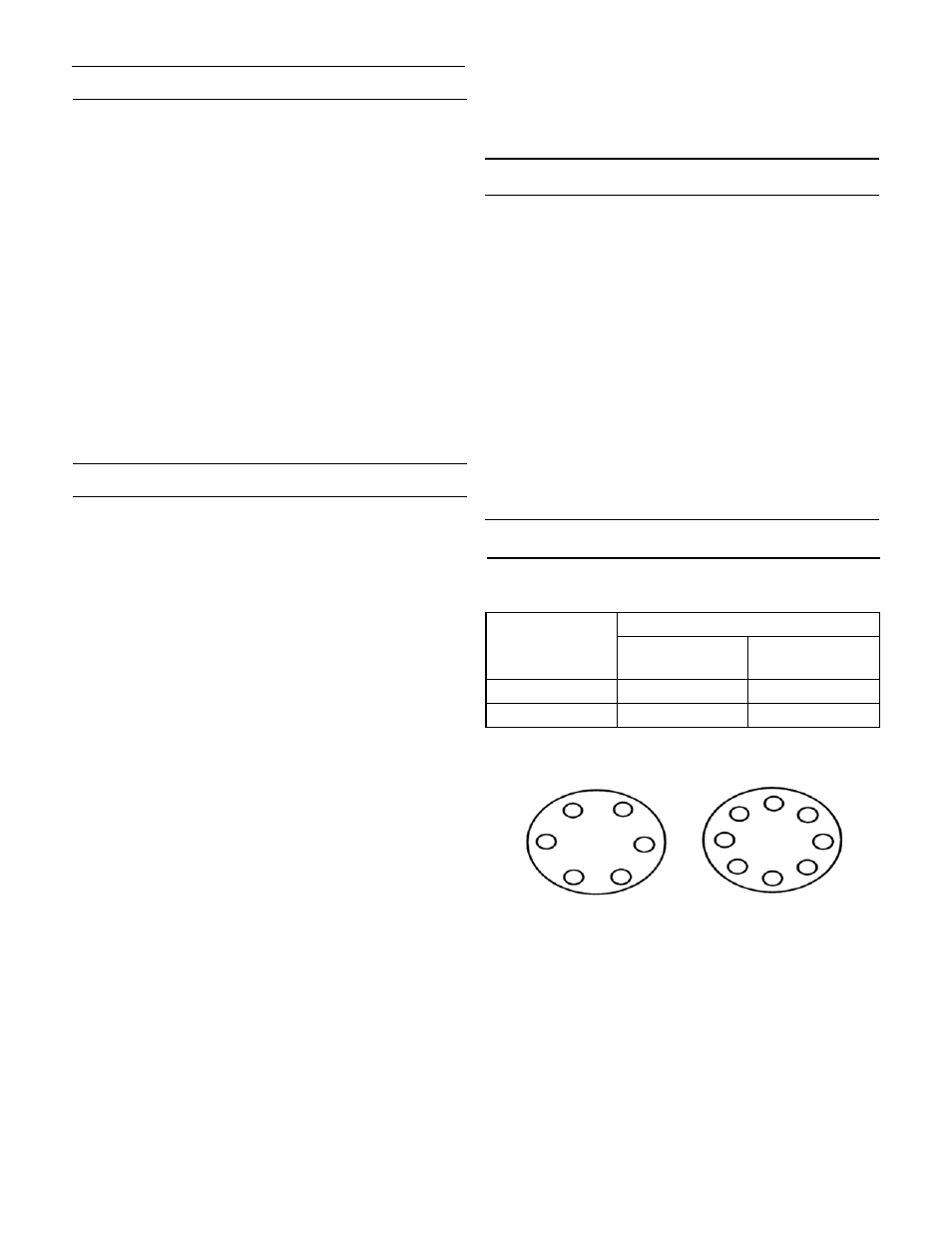
Torque Values
Standard Torque for Cap to Body Bolts (in. - lbs.)
Valve Size
Valve Body Material
Ductile Iron
Bronze
Cast Steel
Stainless Steel
1/4” & 3/8”
70
150
1/2” & 3/4”
110
150
Bolt Pattern / Torquing Sequence
5
3
1
6
4
2
5
3
1
6
4
2
7
8
6 bolts
(or multiples)
8 bolts
(or multiples)