Message content, Modbus tcp/ip option function details – Yaskawa V1000-Series Option SI-EM3D/V Dual Port EtherNet Modbus TCP/IP Technical Manual User Manual
Page 26
n
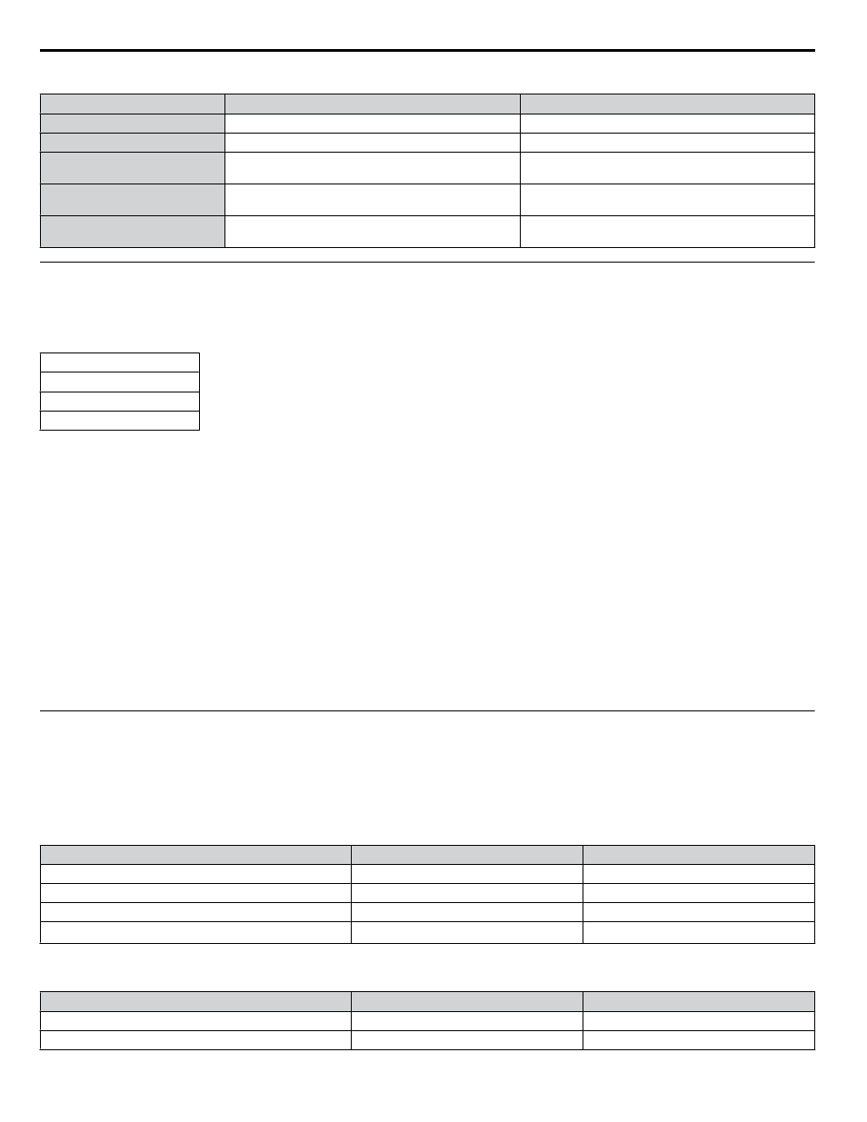
H5-11 and the Enter Command
H5-11 Settings
H5-11 = 0
H5-11 = 1
Drive being replaced
G7, F7
V7
How parameter settings are enabled When the Enter command is received from the master.
As soon as the value is changed.
Upper/lower limit check
Upper/lower limit check is performed taking the settings
of related parameters into account.
The upper/lower limit of the changed parameter is
checked only.
Default value of related parameters Not affected. The settings of related parameters remain
unchanged. They must be changed manually if needed.
The default settings of related parameters are changed
automatically.
Error handling when setting
multiple parameters
Data is accepted even if one setting is invalid. The invalid
setting will be discarded. No error message occurs.
Error occurs if only one setting is invalid. All data sent
are discarded.
u
Message Content
The data section of the Modbus packet contains the Modbus message. In this data section, the master sends commands to the
slave, and the slave responds. The message format is configured for both sending and receiving as shown below, and the length
of data packets depends on the command (function) content.
SLAVE ADDRESS
FUNCTION CODE
DATA
ERROR CHECK
n
Unit Identifier
This field is used for intra-system routing purposes. It is typically used to communicate to a Modbus+ or a Modbus serial line
slave through a gateway between an Modbus TCP/IP network and a Modbus serial line. This field is set by the Modbus master
in the command and must be returned with the same value in the response by the slave. This is sometimes referred to as the
Unit ID. A drive using the option has no gateway functionality.
n
Function Code
When sent by the master, this field identifies the command to be undertaken by the slave. It also identifies the format for the
DATA section of the message. The slave normally echoes this command back to the master in its response message. When
the most significant bit of this field is set in the response message, it signals an error condition has occurred.
n
Data
This field contains multiple bytes of varying length based upon the Function Code for commands and based upon the results
of the command in the response. When sent by the master, this field contains details of the command that the slave will require
to carry out the function. When sent by the slave, this field contains details of the response and sometimes error information.
u
Modbus TCP/IP Option Function Details
n
Read Multiple Registers 03 (03 H)
This function code is used to read the contents of a contiguous block of registers. The command specifies the starting register
and the number of registers. The normal response packs two bytes per register. For each register in the response, the first byte
contains the most significant bits and the second byte contains the least significant bits.
Table 11 Read Multiple Registers Command
Description
Byte
Data (Hex)
Slave Address
1
00 to FF
Function Code
1
03
Starting Register
2
0000 to FFFF
Quantity of Registers
2
N
<1>
<1> N = Quantity of Registers (range is 1 - 16)
Table 12 Read Multiple Registers Response
Description
Byte
Data (Hex)
Slave Address
1
00 to FF
Function Code
1
03
7 Modbus TCP/IP Messaging
26
YASKAWA SIEP YAICOM 17A V1000 Option Dual-Port Modbus TCP/IP SI-EM3D/V Technical Manual