Programming 186, Monitor select, Table a.1 f7 parameter list (continued) – Yaskawa F7 Drive Programming Manual User Manual
Page 194
Programming 186
Monitor Select
o1-01
User Monitor Selection
User Monitor Sel
Selects which monitor will be displayed in the operation menu
upon power-up when o1-02 = 4.
4 to 45
6
A
A
A
A
o1-02
User Monitor Selection After
Power-Up
Power-On Monitor
Selects which monitor will be displayed upon
power-up.
1: Frequency Reference (U1-01)
2: Output Frequency (U1-02)
3: Output Current (U1-03)
4: User Monitor (set by o1-01)
1 to 4
1
A
A
A
A
o1-03
Digital Operator Display
Selection
Display Scaling
0 to
39999
0
A
A
A
A
o1-04
Setting unit for frequency
parameters related to V/F
characteristics
Display Units
Sets the setting units related to V/F pattern frequency related
parameters (E1-04, -06, -09, -11)
0: Hertz
1: RPM
0 to 1
0
-
-
-
A
o1-05
LCD Brightness Adjustment
LCD Contrast
Sets the contrast of the Digital Operator LCD. A setting of “1” is
the lightest contrast and a setting of “5” is the darkest contrast.
0 to 5
3
A
A
A
A
Denotes that parameter can be changed when the Drive is running.
Table A.1 F7 Parameter List (Continued)
Parameter
No.
Parameter Name
Digital Operator Display
Description
Setting
Range
Factory
Setting
Control Method
V/F
V/F
w/
PG
Open
Loop
Vector
Flux
Vector
Sets the units of the Frequency References (d1-01 to
d1-17), the Frequency Reference Monitors (U1-01,
U1-02, U1-05), and the Modbus communication
frequency reference.
0: Hz
1: % (100% = E1-04)
2 to 39: RPM (Enter the number of motor poles).
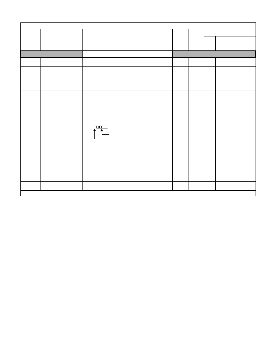
40 to 39999: User display.
Set the number desired at maximum
output frequency.
4 digit number
Number of digits from the right of the
decimal point
Example 1: o1-03 = 12000, will result in frequency
reference from 0.0 to 200.0 (200.0 = Fmax).
Example 2: o1-03 = 21234, will result in frequency
reference from 0.00 to 12.34 (12.34 = Fmax).