Programming 184, Torque limit, Hardware protection – Yaskawa F7 Drive Programming Manual User Manual
Page 192: Table a.1 f7 parameter list (continued)
Programming 184
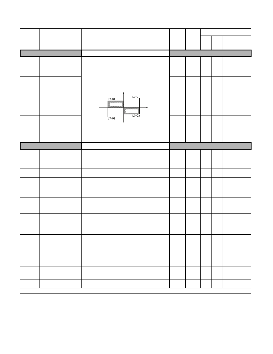
Torque Limit
L7-01
Forward Torque Limit
Torq Limit Fwd
Sets the torque limit value as a percentage of the motor rated
torque. Four individual quadrants can be set.
0 to 300
200%
-
-
A
A
L7-02
Reverse Torque Limit
Torq Limit Rev
0 to 300
200%
-
-
A
A
L7-03
Forward Regenerative
Torque Limit
Torq Lmt Fwd Rgn
0 to 300
200%
-
-
A
A
L7-04
Reverse Regenerative Torque
Limit
Torq Lmt Rev Rgn
0 to 300
200%
-
-
A
A
Hardware Protection
L8-01
Internal Dynamic Braking
Resistor Protection Selection
DB Resistor Prot
Selects the DB protection only when using 3% duty cycle heatsink
mount Yaskawa braking resistor. This parameter does not enable or
disable the DB function of the Drive.
0: Not Provided
1: Provided
0 to 1
0
A
A
A
A
L8-02
Overheat Alarm Level
OH Pre-Alarm Lvl
When the cooling fin temperature exceeds the value set in this
parameter, an overheat alarm (OH) will occur.
50 to
130
95°C
A
A
A
A
L8-03
Overheat Pre-Alarm
Operation Selection
OH Pre-Alarm Sel
Selects the Drive operation upon an OH pre-alarm detection.
0: Ramp to Stop
1: Coast to Stop
2: Fast-Stop
3: Alarm Only
0 to 3
3
A
A
A
A
L8-05
Input Phase Loss Protection
Selection
Ph Loss In Sel
Selects the detection of input current phase loss, power supply volt-
age imbalance, or main circuit electrostatic capacitor deterioration.
0: Disabled
1: Enabled
0 to 1
1
A
A
A
A
L8-07
Output Phase Loss Protection
Ph Loss Out Sel
Selects the detection of output current open-phase.
When applied motor capacity is too small for Drive capacity,
output phase loss may be detected inadvertently. In this case, set to 0.
0: Disabled
1: 1-phase Loss Detection
2: 2/3-phase Loss Detection
0 to 1
1
A
A
A
A
L8-09
Output Ground Fault
Detection Selection
Ground Fault Sel
Enables and disables the Drive’s output ground fault detection.
0: Disabled
1: Enabled
0 to 1
1
A
A
A
A
L8-10
Heatsink Cooling Fan
Operation Selection
Fan On/Off Sel
Controls the heatsink cooling fan operation.
0: Fan On-Run Mode - Fan will operate only when the Drive is
running and for L8-11 seconds after RUN is removed.
1: Fan Always On
- Cooling fan operates whenever the Drive is
powered up.)
0 to 1
0
A
A
A
A
L8-11
Heatsink Cooling Fan
Operation Delay Time
Fan Delay Time
This parameter sets the delay time for the cooling fan turn off after
the run command is removed when L8-10 = 0.
0 to 300
60sec
A
A
A
A
L8-12
Ambient Temperature Setting
Ambient Temp
When the Drive is installed in an ambient temperature exceeding
its rating, the Drive overload (OL2) protection level is adjusted.
45 to 60
45°C
A
A
A
A
Denotes that parameter can be changed when the Drive is running.
Table A.1 F7 Parameter List (Continued)
Parameter
No.
Parameter Name
Digital Operator Display
Description
Setting
Range
Factory
Setting
Control Method
V/F
V/F
w/
PG
Open
Loop
Vector
Flux
Vector
Output torque
Positive torque
Reverse
Negative torque
No. of
motor
rotations
Regen. state
Regen. state
Forward