Wiring in place, 5 installation procedure, Wire gauges and tightening torque – Yaskawa V1000 Option 24 V Power Supply User Manual
Page 28
5 Installation Procedure
28
YASKAWA ELECTRIC TOBP C730600 27B V1000 Option PS-V10 Installation Manual
■
Wire Gauges and Tightening Torque
Table 6 Wire Gauges and Tightening Torque
■
Wire Gauges for Connecting Multiple Drives
The 24 V Power Supply Option can be wired to 10 drives in parallel.
indicates the
proper wire gauges for connecting multiple drives.
Table 7 Wire Gauges for Multiple Drives
◆
Disconnecting the 24 V Power Supply Option (PS-V10S / PS-V10M)
Use this procedure should it become necessary to remove the 24 V Power Supply Option
from the drive.
1. Insert a flat-blade screwdriver into the tabs on the option cover and free the option cover.
Refer to Separate the 24 V Power Supply Option Cover and Mounting Attachment on
2. Remove connection cables by pressing on the connector release tabs at the end of each
cable to unplug the cables.
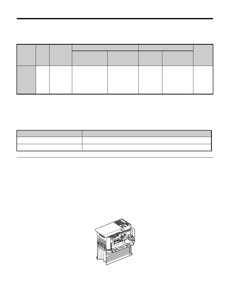
3. Remove the mounting attachment by pressing two tabs in the direction of arrows as shown
in
Figure 23
Figure 23 Removing the Mounting Attachment
Terminal
Number
Screw
Size
Tightening
Torque
(Nxm)
Bare Wire
Pluggable Terminals
Wire
Type
Allowable
Gauges mm
2
(AWG)
Recommended
Gauges mm
2
(AWG)
Allowable
Gauges
mm
2
(AWG)
Recommended
Gauges mm
2
(AWG)
24, 0, FE M2
0.22 to
0.25
Stranded wire,
0.25 to 1.0
(24 to 17)
Single wire, 0.25
to 1.5 (24 to 16)
0.75 (18)
0.25 to 0.5
(24 to 20)
0.5 (20)
Shielded
line, etc.
Connection
Recommended Gauges mm
2
(AWG)
2 to 5 drives wired in parallel
0.25 to 0.5 (24 to 20)
6 to 10 drives wired in parallel
0.5 (20)