Wiring the control circuit terminal, Figure i.15, Serial communication terminals – Yaskawa AC Drive Z1000 HVAC User Manual
Page 30: Wire size and torque specifications
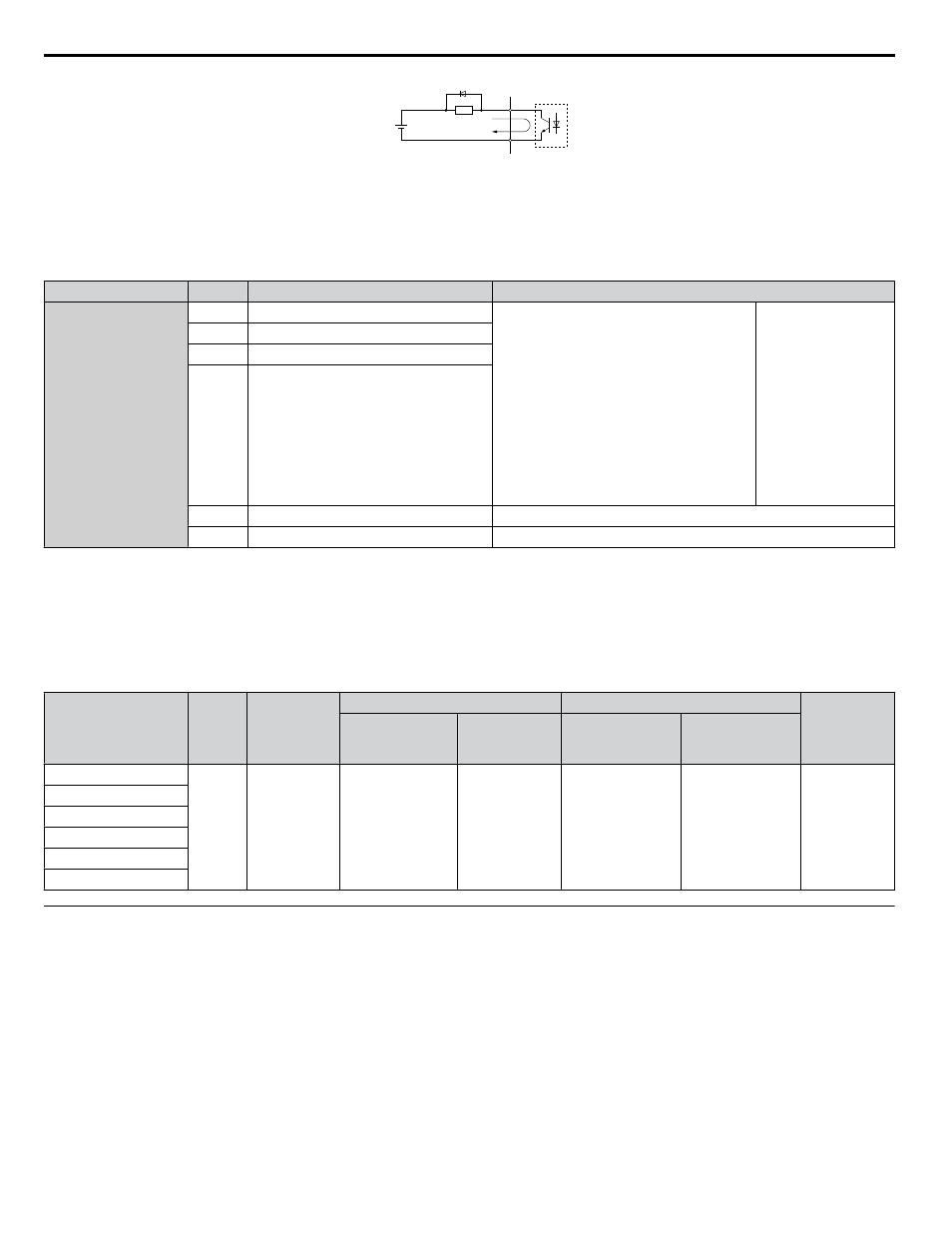
A
B
C
D
A – External power, 48 V max.
B – Suppression diode
C – Coil
D – 50 mA or less
Figure i.15 Connecting a Suppression Diode
n
Serial Communication Terminals
Table i.11 Control Circuit Terminals: Serial Communications
Type
No.
Signal Name
Function (Signal Level)
Serial Communication
(APOGEE FLN,
BACnet, MEMOBUS/
Modbus, or Metasys
N2)
<1>
R+
Communications input (+)
APOGEE FLN, BACnet, MEMOBUS/
Modbus, or Metasys N2 communication: Use
an RS-422 or RS-485 cable to connect the
drive.
• APOGEE FLN
Comm. RS-422/
RS-485, 4.8 kbps
• BACnet Comm.
RS-485, max. 76.8
kbps
• MEMOBUS/
Modbus Comm.
RS-422/RS-485,
max. 115.2 kbps
• Metasys N2 Comm.
RS-422/RS-485, 9.6
kbps
R-
Communications input (-)
S+
Communications output (+)
S-
Communications output (-)
IG
Communications ground
0 V
FE
Option card ground
–
<1> Enable the termination resistor in the last drive in an APOGEE FLN, BACnet, MEMOBUS/Modbus, or Metasys N2 network by setting DIP switch
S2 to the ON position. Refer to the Z1000 User manual TOEPC71061645 for more information on the termination resistor.
n
Wire Size and Torque Specifications
Select appropriate wire type and gauges from
. For simpler and more reliable wiring, use crimp ferrules on the wire
ends. Refer to the Z1000 User manual TOEPC71061645 for ferrule terminal types and sizes.
Table i.12 Wire Gauges
Terminal
Screw
Size
Tightening
Torque
N
•m
(lb. in)
Bare Wire Terminal
Ferrule-Type Terminal
Wire Type
Applicable
wire size
mm
2
(AWG)
Recomm.
wire size
mm
2
(AWG)
Applicable
wire size
mm
2
(AWG)
Recomm.
wire size
mm
2
(AWG)
S1-S7, SC, SN, SP
M3
0.5 to 0.6
(4.4 to 5.3)
Stranded wire:
0.2 to 1.0
(24 to 16)
Solid wire:
0.2 to 1.5
(24 to 16)
0.75 (18)
0.25 to 0.5
(24 to 20)
0.5 (20)
Shielded wire,
etc.
+V, A1, A2, AC
MA, MB, MC
M1-M6
FM, AM, AC
R+, R-, S+, S-, IG
u
Wiring the Control Circuit Terminal
This section describes the proper procedures and preparations for wiring the control terminals.
WARNING! Electrical Shock Hazard. Do not remove covers or touch the circuit boards while the power is on. Failure to comply could result
in death or serious injury.
NOTICE: Separate control circuit wiring from main circuit wiring (terminals R/L1, S/L2, T/L3, -M, +M, -, +1, +3, U/T1, V/T2, W/T3) and other
high-power lines. Improper wiring practices could result in drive malfunction due to electrical interference.
NOTICE: Separate wiring for digital output terminals MA, MB, MC, and M1 to M6 from wiring to other control circuit lines. Improper wiring
practices could result in drive or equipment malfunction or nuisance trips.
NOTICE: Use a class 2 power supply when connecting to the control terminals. Improper application of peripheral devices could result in
drive performance degradation due to improper power supply. Refer to NEC Article 725 Class 1, Class 2, and Class 3 Remote-Control,
Signaling, and Power Limited Circuits for requirements concerning class 2 power supplies.
i.3 Electrical Installation Safety
30
YASKAWA ELECTRIC TOEP YAIZ1U 01A YASKAWA AC Drive – Z1000 Safety Precautions