Yaskawa AC Drive-E7 User Manual
Page 8
1 Supplemental Safety Information - E7 Electronic Bypass
8
IG.E7.05 Yaskawa AC Drive - E7 Electronic Bypass Manual Supplement
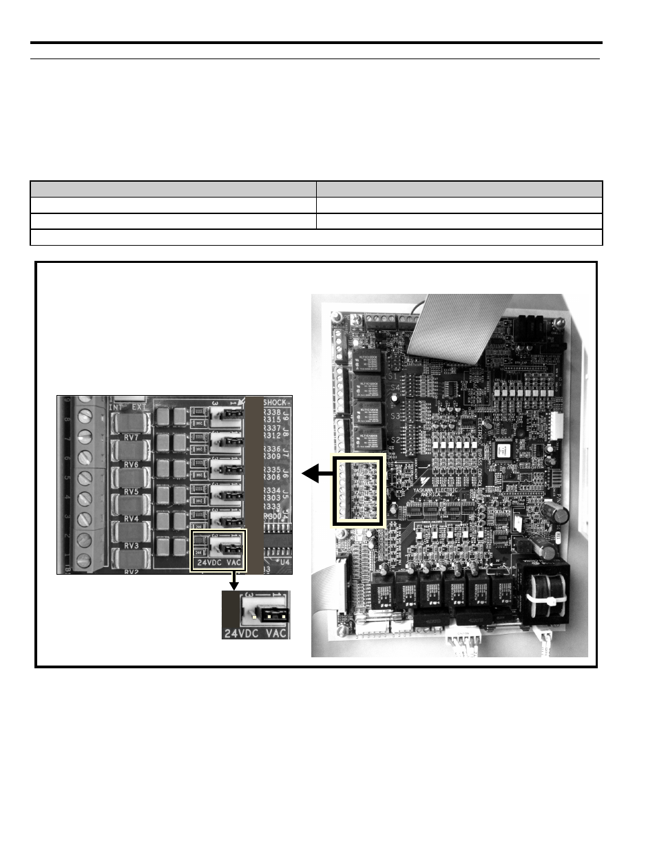
Precautions for Setting PCB A2 Control Circuit Logic Input Voltage
The Control Circuit Logic Inputs on PCB A2 TB1 can be used with either 120 Vac or 24 Vdc input voltage.
(UTC000510 only). Refer to
for details on setting jumpers J4, J5, J6, J7, J8 and J9.
NOTICE: Damage to Equipment. Place all jumpers, J4, J5, J6, J7, J8, J9, in the same matching positions for the correct logic input
voltage at PCB A2 terminal TB1. Failure to comply will result in E7 control circuit damage or in damage to connected peripheral
devices. J4, J5, J6, J7, J8, J9 jumpers are placed in factory default positions 1 & 2 for 120 Vac Control Circuit Logic Inputs.
Table 2 Control Circuit Input Voltage Jumper Settings
Figure 9
Figure 9 Setting Control Circuit Logic Input Voltage with Jumpers J4, J5, J6, J7, J8 and J9
PCB A2 TB1 Input Voltage level
Jumpers J4, J5, J6, J7, J8, and J9, Position
120 Vac Input
1 & 2 (default)
24 Vdc Input
2 & 3
NOTE: All jumpers J4, J5, J6, J7, J8, and J9 must be set on the same setting, either all on Vac or all on 24 Vdc.
-
-
-
-
-
-
-
-
-
-
-
-
127,&( (TXLSPHQW 'DPDJH 3ODFH DOO MXPSHUV
- - - - - - LQ WKH VDPH PDWFKLQJ
SRVLWLRQV IRU WKH FRUUHFW ORJLF LQSXW YROWDJH DW
3&% $ WHUPLQDO 7% )DLOXUH WR FRPSO\ ZLOO UHVXOW
LQ ( FRQWURO FLUFXLW GDPDJH RU LQ GDPDJH WR
FRQQHFWHG SHULSKHUDO GHYLFHV
-XPSHUV DUH SODFHG LQ IDFWRU\ GHIDXOW SRVLWLRQV
IRU 9DF &RQWURO &LUFXLW /RJLF ,QSXWV
3ODFH DOO MXPSHUV - - -
- - - LQ WKH VDPH PDWFKLQJ
SRVLWLRQV
3&% $