Safety circuit installation – Yaskawa AC Drive-E7 User Manual
Page 4
1 Supplemental Safety Information - E7 Electronic Bypass
4
IG.E7.05 Yaskawa AC Drive - E7 Electronic Bypass Manual Supplement
Safety Circuit Installation
On power up, the E7 Electronic Bypass will display a red "Safety Open" LED in the System Status area of the front
control panel if a normally closed (N.C) safety circuit is not been installed between TB1-1 and TB1-9 on PCB A2. This
condition will prevent Drive or Bypass operation.
Figure 1
Figure 1 Safety Open LED Indication
Installing or Deactivating the Safety Circuit
One of these three actions below must be taken prior to equipment start-up to prevent the Safety Open condition.
1. Option 1: Install a N.C. Safety Circuit between TB1-1 and TB1-9 on PCB A2 according to
.
2. Option 2: Install a jumper between TB1-1 and TB1-9 on PCB A2 according to
. This method should be used if
a Safety Circuit will be added later in the installation
.
3. Option 3: De-activate these terminals by moving DIP switch S2-7 to the ON position (toward the enclosure door)
according to
. This solution is only suggested if a Safety Circuit will never be applied to the drive system
.
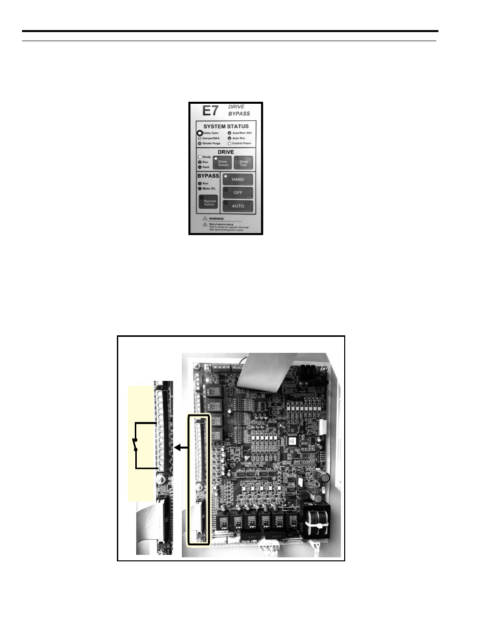
Figure 2
Figure 2 Option1: Normally Closed (N.C.) Safety Circuit Installation
6DIHW\ &LUFXLW
1RUPDOO\ &ORVHG 1&
7% WR 7%
7%
7%
7%
3&% $