Applicability – Yaskawa AC Drive-E7 User Manual
Page 3
1 Supplemental Safety Information - E7 Electronic Bypass
IG.E7.05 Yaskawa AC Drive - E7 Electronic Bypass Manual Supplement
3
1
Supplemental Safety Information - E7 Electronic Bypass
Applicability
This document is shipped with each E7L, E7N, E7B with Y Option, and E7B with T Option to call attention to the
installer that certain wiring of the safety and interlock circuits is required. The contents of this supplement pertain to
Yaskawa drive products listed in
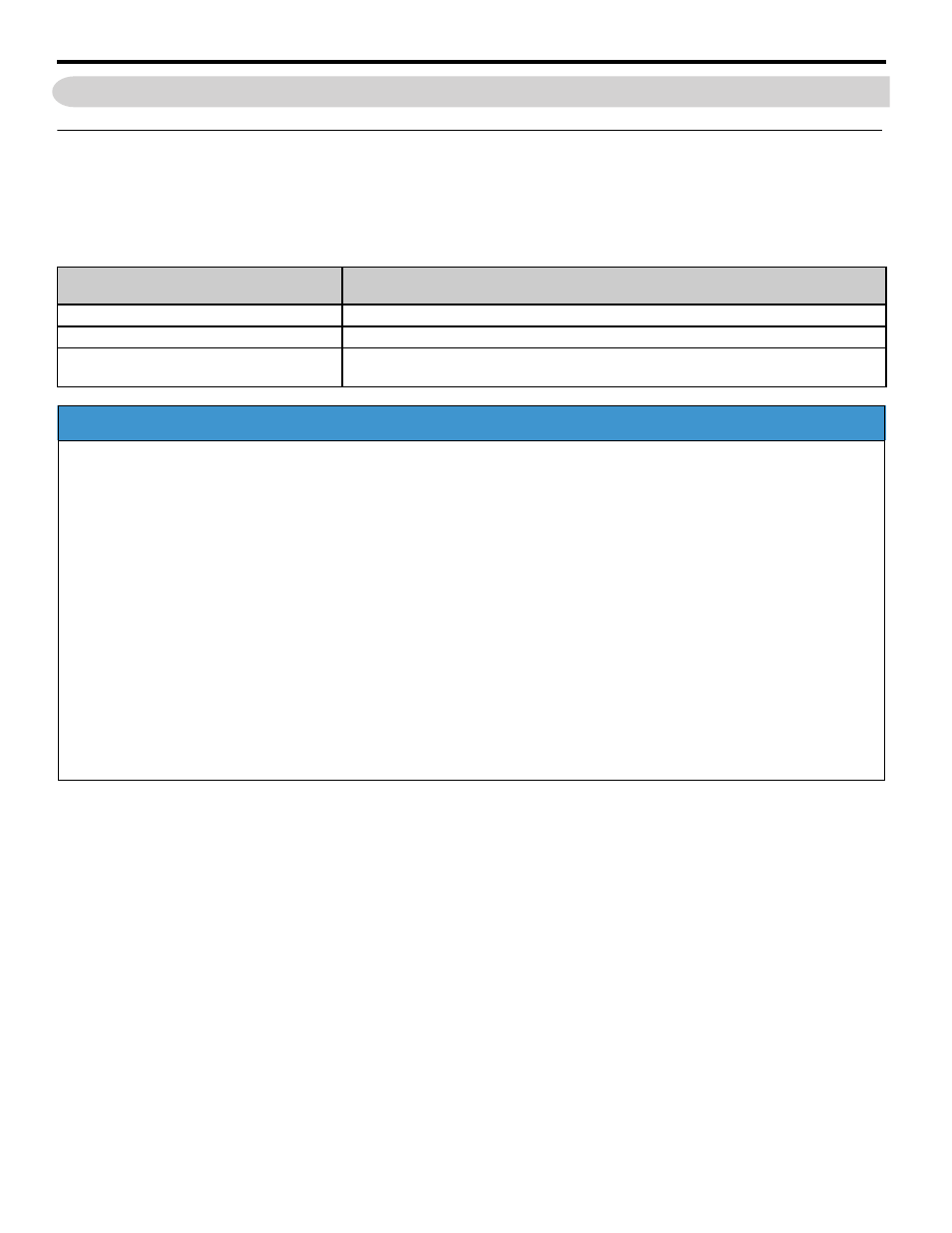
Table 1 Affected Models
Yaskawa
Product
Description
E7L
Applicable models are Yaskawa Bypass units definedby model numbers E7L_ _ _ _.
E7N Narrow Bypass Package
Applicable models are Yaskawa Bypass units definedby model numbers E7N_ _ _ _.
E7B with Y Option ot T Option
Applicable models are Yaskawa Bypass units definedby model numbers E7B_ _ _ _
with Y Option or T option installed.
NOTICE
Equipment Damage - Precautions for Setting Control Circuit Logic Inputs Jumpers
J4, J5, J6, J7, J8 and J9
Place all jumpers, J4, J5, J6, J7, J8, J9, in the same matching positions for the correct logic input voltage at PCB A2
terminal TB1. Failure to comply will result in E7 control circuit damage or in damage to connected peripheral devices.
J4, J5, J6, J7, J8, J9 jumpers are placed in factory default positions 1 & 2 for 120 Vac Control Circuit Logic Inputs.
Equipment Failure to Operate - Precautions for Safety Circuit Installation
TB1-1 to TB1-9
Install a jumper or a normally closed (N.C.) circuit at PCB A2 terminals TB1-1 to TB1-9 to allow drive or bypass
operation and to prevent a Safety Open fault at power-up. Failure to comply will prevent drive or bypass operation.
Equipment Failure to Operate - Precautions for BAS Interlock Circuit Installation
TB1-3 to TB1-9
Install a jumper or a normally closed (N.C.) circuit at PCB A2 terminals TB1-3 to TB1-9 to allow drive or bypass
operation and to prevent a Safety Open fault at power-up. Failure to comply will prevent drive or bypass operation.