Yaskawa G5 PID for Trim Control User Manual
Page 8
Date: 07/01/04, Rev: 04-07
Page 8 of 12
TM.G5SW.012
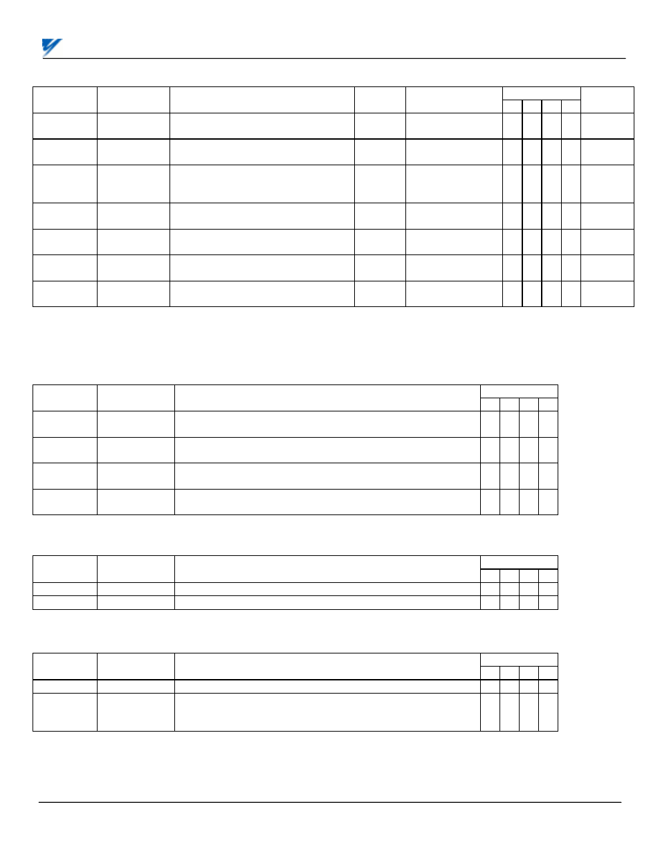
Additions to Table A1-10
(Appendix 1)
(2)
Availability
(4)
Parameter
Number
Monitor Item
Description
Display
Unit
Analog Monitor
Output Level
0 1 2 3
Modbus
Address
U1-50
Feedback
Monitor
Feedback Level
0.01 V
10V / 10V
feedback signal
A A
A
A
00D0H
U1-51 PID
Error
Difference between setpoint and
feedback
0.01%
10V / max. output
freq. (E1-04)
A A
A
A
00D1H
U1-52 PID
Output
Output of the PID control algorithm
before its added into the main
frequency reference
0.01%
10V / max. output
freq. (E1-04)
A A
A
A
00D2H
U1-53
Proportional
Value
Output value of just the proportional
portion of the PID algorithm
0.01%
10V / max. output
freq. (E1-04)
A A
A
A
00D3H
U1-54
Integral
Value
Output value of just the integral
portion of the PID algorithm
0.01%
10V / max. output
freq. (E1-04)
A A
A
A
00D4H
U1-55
Derivative
Value
Output value of just the derivative
portion of the PID algorithm
0.01%
10V / max. output
freq. (E1-04)
A A
A
A
00D5H
U1-56 PID
Setpoint
Actual PID setpoint
(Analog value + b5-07)
0.01V
10V / 10V
setpoint
A A
A
A
00D6H
NOTE: The standard software PID monitors (U1-24: PID Feedback, U1-36: PID Input, U1-37: PID Output, and U1-38: PID
Setpoint) are not used in this software. Please use monitors U1-50 through U1-56.
Addition to Table 5-2 Multi-Function Input Terminal Data Settings
(Section 5.32)
(2)
Parameters H1-01 thru H1-06 and terminals 3 thru 8.
Availability
(4)
Data Function
Description
0 1 2 3
30
PID Integral
Reset
Closed = Reset integrator to zero
See Paragraph 5.36F
B B B
B
80 Integral
Hold
Closed = Hold integrator at its present level
See Paragraph 5.36F
B B B
B
81
Positive
Integral Hold
Closed = Will allow integrator level to decrease, but not
increase. See Paragraph 5.36F
B B B
B
82
Negative
Integral Hold
Closed = Will allow integrator level to increase, but not
decrease. See Paragraph 5.36F
B B B
B
Addition to Table 5-3 Multi-Function Output Terminal Data Settings
(Section 5.33)
(2)
Parameters H2-01 thru H2-03 and terminals 9, 10, 25, 26 & 27. Plus DO-02C option card F5-01 & F5-02.
Availability
(4)
Data Condition
Signal
Level
0 1 2 3
40 High
Position
Closed When PID Feedback is above High position b5-10
B B B B
41 Low
Position
Closed When PID Feedback is below Low position b5-11
B B B B
Addition to Section 5.30 Multi-Function Analog Input Terminal Data Settings
(2)
Parameters H3-05 & H3-09 and terminals 16 & 14.
Availability
(4)
Data Function
Description
0 1 2 3
20
PID Setpoint
Provides a setpoint signal for use with PID control.
B B B
B
21
PID Feed-
back Analog
Input Bias
Mathematically adds to the feedback signal when using PID
control.
B B B
B
(2)
GPD515/G5 Technical Manual TM4515
(4)
Capability to view and set specific parameters is dependent upon the Access Level (A1-01) and Control Method (A1-
02: 0 = V/f, 1 = V/f w/PG, 2 = Open Loop Vector, 3 = Flux Vector) the drive is programmed for. Each column represents
the minimum Access Level for a given Control Method: 0 = Operation only; Q = Quick-start; B = Basic; A = Advanced; - =
not available.