New multi-function analog input setting, New multi-function analog output setting, New multi-function digital input setting – Yaskawa G5 Output Voltage PID User Manual
Page 2: Modbus rtu modifications
Date: 07/01/04, Rev: 04-07
Page 2 of 6
TM.G5SW.022
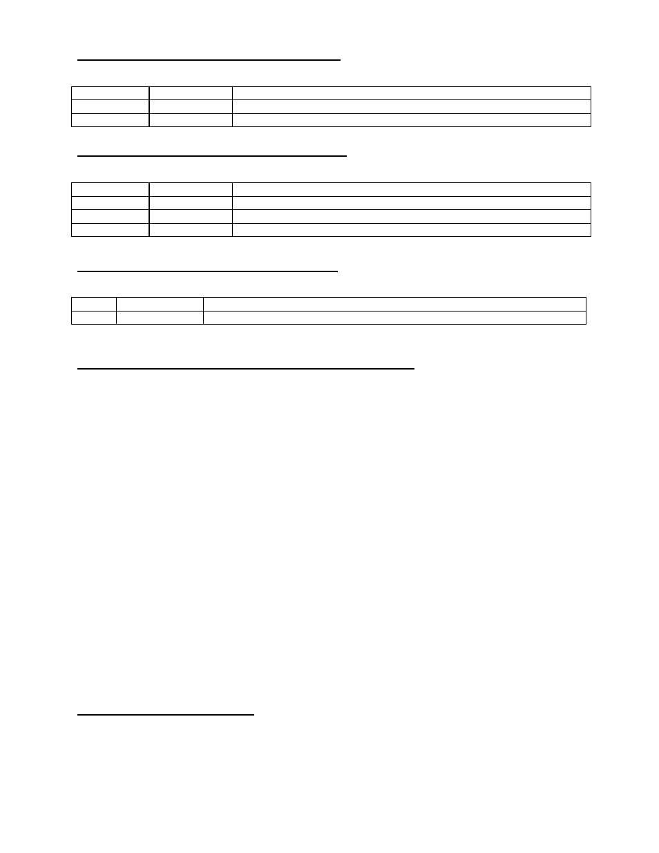
New Multi-Function Analog Input Setting
For Constants H3-05 or H3-09
Setting Display
Description
20
Aux PID VRef
Analog voltage setpoint
21
Aux PID Vfb
Analog voltage feedback
New Multi-Function Analog output Setting
For Constants H4-01 or H4-04
Setting Display
Description
35
Aux PID VRef
PID Voltage Setpoint
36
Aux PID Vfb
PID Voltage Feedback
37
Aux PID Output PID Output
New Multi-Function Digital Input Setting
For Constants H1-01 through H1-06
Setting Display
Description
80
Aux PID Off
When this input is closed, the voltage setpoint becomes the output voltage reference.
Default Parameters Differing from Standard Software
A1-01 = 4
Advanced Access Level
A1-02 = 0
V/f Mode
B1-01 = 0
Operator
B1-02 = 2
Serial Communications
B1-04 = 1
Reverse Disable
C1-01 = 0
Acceleration Time 1
C1-02 = 0
Deceleration Time 1
C2-01 = 0
S-Curve
C2-02 = 0
S-Curve
C2-03 = 0
S-Curve
C4-01 = 0
Torque Compensation Disabled
C7-01 = 0
Hunting Prevention Disabled
E1-04 = 65
Maximum Frequency
E1-05 = 120.0
Maximum Voltage
E1-06 = 50.0
Base Frequency
E1-08 = 0
Mid Voltage A
E1-10 = 0
Minimum Voltage
H1-06 = 80
Terminal 8, Aux PID off
H3-03 = 0
Terminal 13 bias
H3-05 = 20
Terminal 16, Aux PID VRef
H3-08 = 0
Terminal 14, 0-10V
H3-09 =21
Terminal 14, Aux PID Vfb
H4-04 = 06
Terminal 23, Output voltage
H4-05 = 1.00
Terminal 23 gain
H5-01 = 3
Serial Comm Station Address
H5-03 = 2
Odd Parity
H5-05 = 0
Serial Comm fault det: Disabled
L2-01 = 2
CPU Power Active
L3-01 = 0
Accel Stall Prevention Disabled
L3-04 = 0
Decel Stall Prevention Disabled
L3-05 = 0
Running Stall Prevention Disabled
L5-01 = 2
Number of auto restarts
L8-07 = 0
Disable
O1-02 = 2
Output frequency
O2-01 = 0
Disable
O2-02 = 0
Disable
O2-08 = 1
Running Time
Factory Level Access
C8-12 = 5 ms
C8-13 = 1
2 Phase Modulate
C8-16 = 0.0 us
ModBus RTU Modifications
The standard software address to initiate an enter command is 0xfffd. This software extends that to include the use
0x4000 for this purpose. The Modbus RTU function 6 write command has also been implemented.