Yaskawa F7 Drive Output Voltage PID User Manual
Page 7
Date: 05/05/05, Rev: 05-05
Page 7 of 8
TM.F7SW.061
4.4 Faults
Fault Display
Description
Cause
Countermeasures
OPE12
Energy Save ON
The energy savings feature
(B8 Group) was enabled at
the same time the output
voltage PID controller was
enabled.
Energy savings was
enabled (B8-01 = 1) when
parameter P1-01 > 0.0
Note: V/Hz control mode
only (A1-02 = 0).
Set
B8-01 = 0 or
P1-01 = 0.0VAC
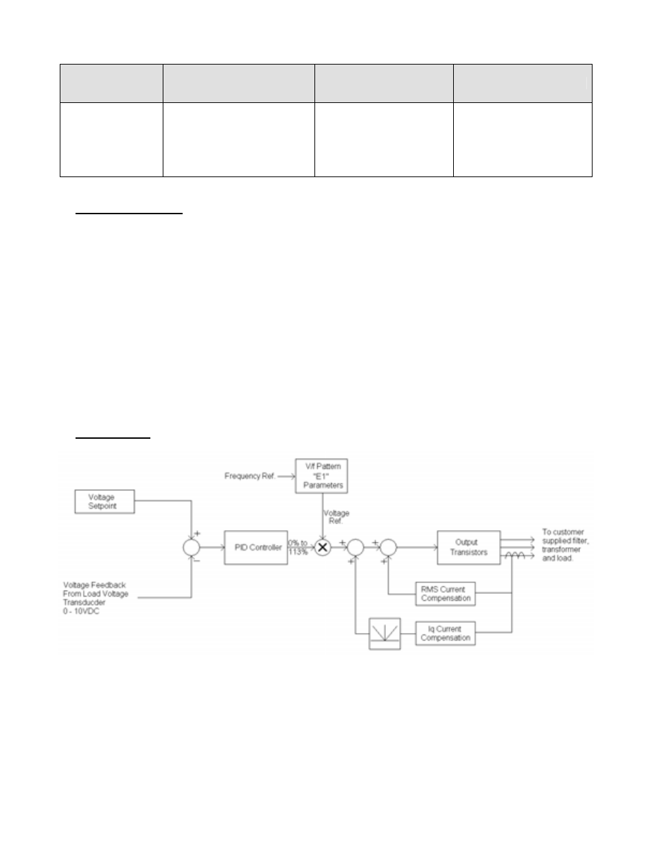
5.0 Function Description
An independent PID controller is added, the output of which will trim the output voltage. The trim range is
+13% to –100% of the output voltage as commanded by the V/Hz pattern. There are also two dynamic
functions available that allow output voltage boost based upon the RMS output current (Iac) and the secondary
(Iq) current. These are useful in regulating the output voltage during sudden load changes. These functions
can each add up to 400VAC (200VAC for 240V drives) of additional voltage (limited by the input voltage to the
drive).
The intent of this software is to control the voltage after a filter / transformer network; as the output of the drive
is NOT used to drive a motor, but instead used operate as a power supply operating at a fixed frequency. An
external customer-supplied transducer is required that converts the load terminal voltage into a 0-10VDC or 4-
20mA analog signal, which is used as the feedback to the PID controller.
The multi-function digital input (H1-0X) functions that normally control the drive’s standard PID controller (B5
group) also control the Output Voltage PID controller. These functions include: PID Disable (H1-0X = 19), PID
Integral Reset (H1-0X = 30), and PID Integral Hold (H1-0X = 31).
6.0 Block Diagram