Yaskawa F7 Drive Output Voltage PID User Manual
Page 4
Date: 05/05/05, Rev: 05-05
Page 4 of 8
TM.F7SW.061
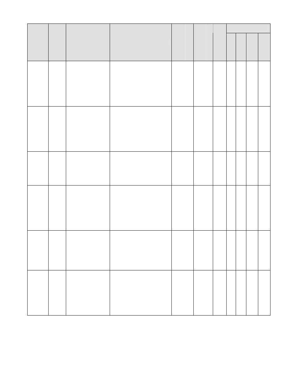
4.1 Parameters (continued)
Control Mode *1
Paramete
r
Numb
er
Modbu
s
Addre
ss
Parameter Name
Digital Operator
Display
Description
Ran
ge
Default
Cha
nge
Duri
ng Run
V/f
V/f w/ P
G
Open Lo
op
Vector
Flu
x
Vector
P1-02 601h
Output Voltage
PID Gain
Output V Gain
Sets the proportional gain
of the output voltage PID
controller. A larger
setting equals more
response.
Note: A setting of 0.00
disables this feature.
0.0 ~
25.00
1.00 Yes A - - -
P1-03 602h
Output Voltage
PID Integral Time
Output V I Time
Sets the integral time of
the output voltage PID
controller. A smaller
setting equals more
response.
Note: A setting of 0.00sec
disables this feature.
0.00 ~
360.00
sec
1.00 Yes A - - -
P1-04 603h
Output Voltage
PID Integral Limit
Output V I Lmt
Sets the limit of the output
voltage PID integrator.
Note: 100% = Voltage
reference from V/Hz
pattern.
0.0 ~
100.0
%
100.0 Yes A - - -
P1-05 604h
Output Voltage
PID Derivative
Time
Output V Deriv T
Sets the derivative time of
the output voltage PID
controller.
A larger setting equals
greater response.
Note: A setting of 0.00
sec disables this feature.
0.00 ~
10.00
sec
0.00 Yes A - - -
P1-06 605h
Output Voltage
PID Limit
Output V Limit
Sets the overall limit of
the output voltage PID
controller (P + I + D).
Note: 100% = Voltage
reference from V/Hz
pattern.
0.0 ~
100.0
%
100.0 Yes A - - -
P1-07 606h
Analog Input Full
Scale Voltage
Ana Full Scale V
Sets the scaling for the
multi-function analog
input function “Output
Voltage Feedback” (H3-
0X = 20).
Note: 10VDC / 20mA
feedback = P1-07
0.0 ~
1000.0
VAC
600.0 No A - - -
*1: Access Level (A1-01): Q = “Quick Start”, A = “Advanced”, F = “Factory”.
*2: Moved from the “Factory” access level to the “Advanced” access level. Consult the factory before adjusting.