Wiring examples of pg-x2 and pg-w2 option cards, Examples 1 & 2: open or closed loop, Example 3: closed loop with orientation encoder – Yaskawa F7 Drive Technical Manual Orientation User Manual
Page 13
Date: 03/03/06, Rev: 06-03
Page 13 of 16
TM.F7SW.063
6.2 Required Components
The exact application will dictate the required configuration of components. The following table can be
used to determine the components needed. All encoders must have quadrature feedback (A and B
channels with compliments). The orientation encoder must also have a marker pulse (referred to as the Z
or C pulse). If not, an external switch must be used to locate the marker position.
6.2.1 Encoder Feedback Requirements
Example
Encoder Feedback
Option Card
Possible Encoder
PPR *2
Encoder Power
Supply Voltages
Orientation
Encoder PPR
Motor
Encoder PPR
1 PG-X2 512-8192
5VDC,
12VDC
Yes
No
2 PG-X2 512-8192
5VDC,
12VDC
Yes
(same encoder is used for both)
3 PG-W2
*3 512-8192 12VDC
Yes
Yes
*2 The maximum input frequency of the PG-X2 and PG-W2 option cards is 300kHz. Ensure that the
combination of the maximum output frequency (E1-04) and the encoder PPR will not exceed 300kHz.
Otherwise, loss of control could occur.
*3 The PG-W2 has a maximum power supply of 200mA. An external power supply may be required for one
of the encoders if the combined power draw exceeds 200mA.
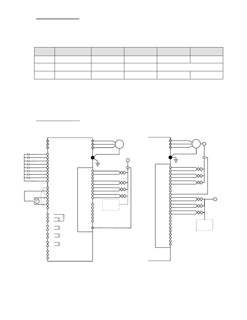
6.3 Drive Wiring Examples
Wiring Examples of PG-X2 and PG-W2 Option Cards
IM
12VDC Supply
Common
A+
A-
B+
B-
1
2
3
4
5
6
7
8
9
GND
P
G
-X
2 O
pt
ion Card
Orientation
Encoder
T1
T2
T3
F7
L1
L2
L3
S1 Forward Run
S2 Reverse Run
S3 Orient
S4 Reset
S5 MSBit 4
S6 Bit 3
S7 Bit 2
S8 LSBit 1
SN Common
E (G)
A1 Input (0 to +/- 10VDC)
A2 Input (4 to 20mA )
+V Supply (+15VDC)
A3 Input (0 to +/- 10VDC)
AC Common
TA
2
(Mo
ni
to
r)
TA
1
(
C
hannel
1
Inpu
t)
Motor
Examples 1 & 2: Open or
Closed Loop
1
2
3
4
5
6
M3
M4
MA
MB
MC
-V Supply (-15VDC)
FM Output (0 to +/- 10VDC)
AM Output (0 to +/- 10VDC)
AC Common
Shield
TA
3
Speed Reference
Z-
Z+
External
Marker
Switch
41: Home
Position
40: Orient
Complete
IM
12VDC Supply
Common
A+
A-
B+
B-
1
2
3
4
5
6
7
8
9
GND
P
G
-W2 O
pt
ion
Card
T1
T2
T3
Motor
11
12
13
14
15
16
A+
A-
B+
B-
10
17
18
19
20
21
22
23
24
Z-
Z+
Motor
Encoder
Orientation
Encoder
Note: An external power supply may be
required. The PG-W2 has a 200mA
power supply. Check the rated current of
both encoders.
Example 3: Closed Loop
with Orientation Encoder
External
Marker
Switch
M1
M2
M5
M6
Fault