Devicenet™ with adr option kit cm012 – Yaskawa DeviceNet with ADR Option Kit CM012 User Manual
Page 6
Yaskawa Electric America, Inc. –
www.yaskawa.com
IG.AFD.16, Page 6 of 7
Date: 06/15/2007 Rev: 07-06
DeviceNet™ With ADR Option Kit
CM012
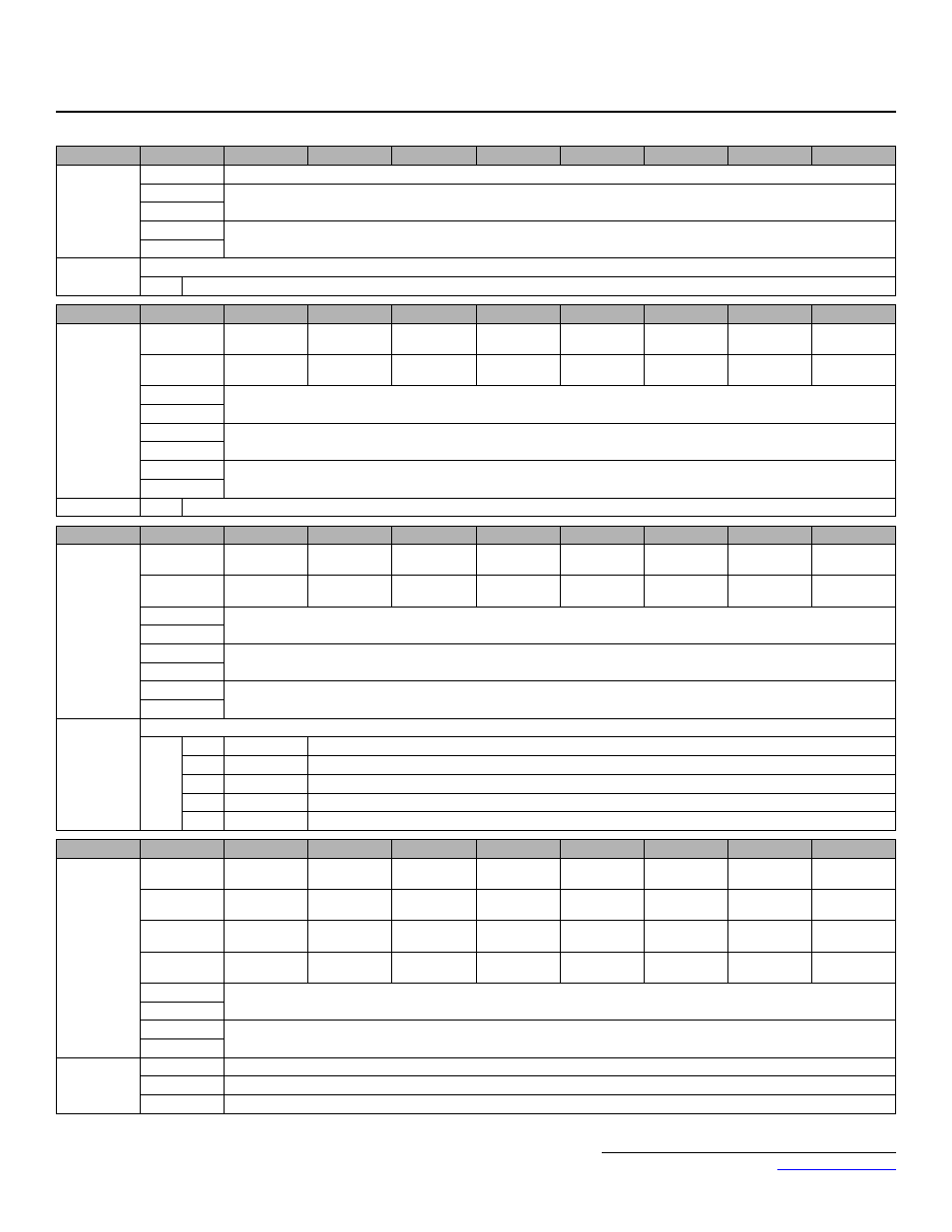
Instance
Byte
Bit 7
Bit 6
Bit 5
Bit 4
Bit 3
Bit 2
Bit 1
Bit 0
150 (96h)
Modbus
Message
5 Bytes
0
Function Code
1
1
Register Number
2
3
Data
4
Notes:
Refer to input assembly instance 100 (64h) for command.
1
A Modbus message error is returned if the function code has the MSB (bit 80h) set.
Instance
Byte
Bit 7
Bit 6
Bit 5
Bit 4
Bit 3
Bit 2
Bit 1
Bit 0
151 (97h)
Standard
Control
8 Bytes
0
Fault
Alarm
Drive Ready
Speed Agree
Fault Reset
Running in
Reverse
Zero Speed
Running
Forward
1
Zero Servo
Complete
1
–
Terminal
M5-M6
Terminal
M3-M4
Terminal
M1-M2
Local Mode
Power Loss
Ride Thru
OPE Error
2
Output Frequency (Scaled by Parameter o1-03) (U1-02)
3
4
Torque Reference (0.1%) (FVC Mode Only, A1-02 = 3) (U1-09)
5
6
Output Current (0.01A or 0.1A, Based on Drive Capacity) (U1-03)
7
Note:
1
Flux Vector Control Mode Only (A1-02 = 3)
Instance
Byte
Bit 7
Bit 6
Bit 5
Bit 4
Bit 3
Bit 2
Bit 1
Bit 0
155 (9Bh)
Enhanced
Control/
Modbus
Message
8 Bytes
0
Fault
Alarm
Drive Ready
Speed Agree
Fault Reset
Running in
Reverse
Zero Speed
Running
Forward
1
Terminal
M5-M6
Terminal
M3-M4
Terminal
M1-M2
Local Mode
Function Bit
2
1
Function Bit
1
1
Undervoltage
OPE Error
2
Output Frequency (Scaled by Parameter o1-03) (U1-02)
3
4
Register Number
5
6
Data
7
Notes:
Refer to input assembly instance 105 (69h) for command.
1
Bit 1
Bit 2
Function Description
0
0
None
0
1
Message Accepted
1
0
Message Error
1
1
Complete
Instance
Byte
Bit 7
Bit 6
Bit 5
Bit 4
Bit 3
Bit 2
Bit 1
Bit 0
157 (9Dh)
Standard
DI/DO
Control
8 Bytes
0
Fault
Alarm
Drive Ready
Speed Agree
Fault Reset
Running in
Reverse
Zero Speed
Running
Forward
1
Zero Servo
Complete
3
–
–
–
–
Local Mode
Undervoltage
OPE Error
2
Terminal
S10
2
Terminal S9
2
Terminal S8
1
Terminal S7
Terminal S6
Terminal S5
Terminal S4
Terminal S3
3
Terminal
P4-C4
2
Terminal
P3-C3
2
Terminal
M5-M6
Terminal
M3-M4
Terminal
M1-M2
–
Terminal S12
2
Terminal S11
2
4
Analog Input Terminal A1 Monitor (Terminal 13 on G5) (0.1%) (U1-16)
5
6
Output Frequency (Scaled by Parameter o1-03) (U1-02)
7
Notes:
1
G5, F7, and G7 only
2
G7 Only
3
Flux Vector Control Mode Only (A1-02 = 3)