Warning – Yaskawa DS387 User Manual
Page 9
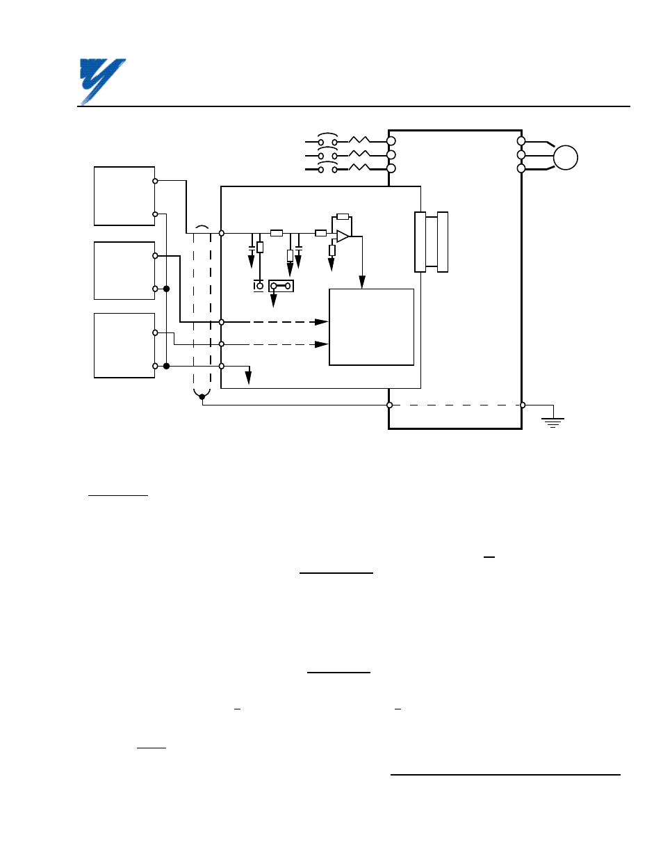
Figure B3. Interconnection for Analog Speed Reference (AI-14B) Circuit in VCD 703
2CN
12 (OR 32)
VCD
703
AI-14B BOARD
L1
L2
L3
T1
T2
T3
E
I M
MOTOR
MCCB
SHIELD
0V
HIGH ACCURACY
VOLTAGE
DEVICES
0V
2CN
TC2
TC3
0-±10V
0V
0-±10V
0-±10V
0V
TC1
1000
pF
10K
500
V
C
TC4
20K
1 µF
20K
*
*
*
TC2 AND TC3 INPUT CIRCUITS
ARE IDENTICAL TO TC1.
SIGNAL
FUNCTIONS
DETERMINED BY
SETTING
OF Sn-25
(SEE TABLE B4)
B7. Adjustments
There are no adjustments to be made on the Analog Speed Reference option; however, the VCD 703 will have to be
reprogrammed for the input requirement of the remote device and the reversing or non-reversing requirement of the
specific application.
WARNING
IF THE APPLICATION REQUIRES THAT REVERSE MOTOR
ROTATION BE PROHIBITED, Sn-05 MUST BE SET TO X X 1 X
SO THAT THE MOTOR WILL STOP ANY TIME POLARITY OF THE
SPEED REFERENCE GOES NEGATIVE.
IMPORTANT
For the Analog Speed Reference circuit to function properly, system constant Sn-04
must be set to XXX 0 and Sn-08 must be set to XXX 0 (input to AI-14B replaces
auto speed reference signal).
(1) GAIN: Adjustment of the gain of the speed or torque reference commands is done by changing
the associated VCD 703 constants; see Table B3.
Yaskawa Electric America, Inc-www.drives.com
02Y00025-0296 Page 9 OF 14
REL. 08/23/91
ANALOG SPEED REFERENCE
(BIPOLAR) (AI-14B) MODEL DS387