Yaskawa DS387 User Manual
Page 3
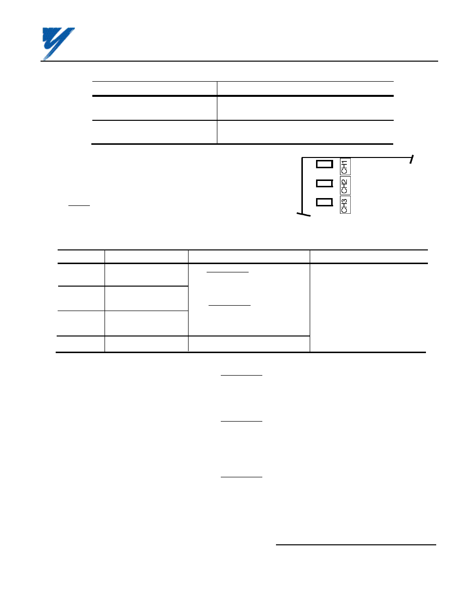
Table A1. AI-14B Specifications in GPD 515
Parameter
Value
Input Signal Level
0 to ±10V DC (Input Impedance: 20k
Ω
)
0 to 20mA (input impedance : 500
Ω)
Input Resolution
Voltage: 13 bits (1/8192) plus sign (polarity)
Current: 1/6554
Table A2. Terminal Functions of AI-14B
Terminal
Function
Signal Level
Notes
TC1
Analog voltage/current
Voltage Input:
— Input Resolution:
input
Input voltage: 0 to ±10V/0 to ±100%
Voltage: 1/8192 (13 bits) plus
Input impedance: 20K
Ω
sign (polarity)
TC2
Analog voltage/current
Current: 1/6554
input
Current Input:
Input current: 0 to 20mA/0 to ±100%
— Signal Linearity: ±0.1%
TC3
Analog voltage/current
Input impedance: 500
Ω
input
— Terminal screws are metric
size M3.
TC4
Signal common
0V
A5. Determine whether a voltage or current
signal will be inputted on each of the channels of
the AI–14B board, and set selection jumpers
accordingly (see Figure A2).
A6. Wiring. See Figure A3 for Analog Speed
Reference connections. See Table A2 for terminal
functions.
Figure A2. Voltage/Current Selection on AI-14B
• • •
V C
• • •
V C
• • •
V C
PART OF
AI-14B
BOARD
ALL JUMPERS
(SHORTING
PLUGS) SHOWN
IN POSITION
FOR CURRENT
INPUT
CAUTION
KEEP ANALOG SPEED REF. (I.E. CONTROL CIRCUIT) WIRING
SEPARATE FROM MAIN CIRCUIT INPUT/OUTPUT WIRING.
CAUTION
TO PREVENT ERRONEOUS OPERATION CAUSED BY NOISE
INTERFERENCE, USE SHIELDED CABLE FOR CONTROL WIRING,
AND LIMIT DISTANCE TO 10M (33 FEET) OR LESS.
CAUTION
IF ANY OF THE CONTROL SIGNAL INPUT TERMINALS (TC1 THRU
TC3) ARE NOT USED, JUMPER THEM TO 0V TERMINAL (TC4).
Yaskawa Electric America, Inc-www.drives.com
02Y00025-0296 Page 3 OF 14
REL. 08/23/91
ANALOG SPEED REFERENCE
(BIPOLAR) (AI-14B) MODEL DS387