Warning – Yaskawa DS387 User Manual
Page 13
2CN
12
GPD
503
AI-14B BOARD
L1
L2
L3
T1
T2
T3
E
I M
MOTOR
MCCB
SHIELD
0V
HIGH ACCURACY
VOLTAGE / CURRENT
DEVICES
0V
2CN
TC2
TC1
TC3
TC4
14 BIT
A/D
14 BIT
A/D
14 BIT
A/D
1 / 10
FREQ.
REF
0-±10V
or 4-20mA
0V
0-±10V
or 4-20mA
0-±10V
or 4-20mA
0V
X
+
+
+
1 / 10
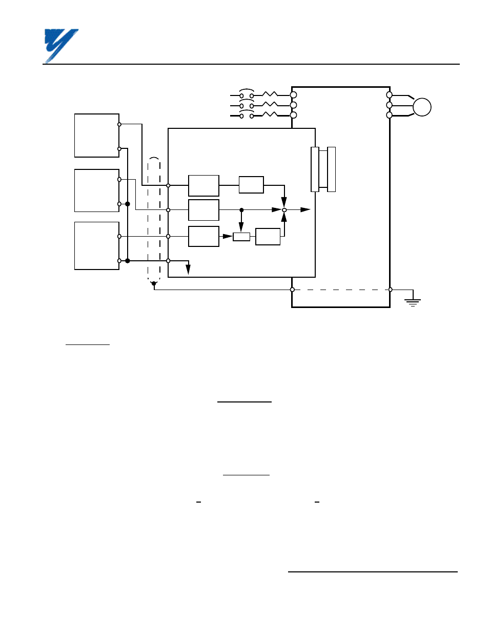
Figure C3. Interconnection for Analog Speed Reference (AI-14B) Circuit in GPD 503
C7. Adjustments.
There are no adjustments to be made on the Analog Speed Reference option; however, the GPD 503 will have to
be reprogrammed for the input requirement of the remote device and the reversing or non-reversing requirement
of the specific application.
WARNING
IF THE APPLICATION REQUIRES THAT REVERSE MOTOR
ROTATION BE PROHIBITED, Sn-25 MUST BE SET TO X X X 1
SO THAT THE MOTOR WILL STOP ANY TIME POLARITY OF
THE SPEED REFERENCE GOES NEGATIVE.
IMPORTANT
For the Analog Speed Reference circuit to function properly, system constant
Sn-04 must be set to XXX 0 and Sn-08 must be set to XXX 0 (input to AI-14B
replaces auto speed reference signal).
Adjustment of the bias and gain of the frequency command are done by changing the associated GPD 503
constants; see Figure C4 and Table C3.
Yaskawa Electric America, Inc-www.drives.com
02Y00025-0296 Page 13 OF 14
REL. 08/23/91
ANALOG SPEED REFERENCE
(BIPOLAR) (AI-14B) MODEL DS387