Yaskawa DS387 User Manual
Page 2
Section A: Installation in a GPD 515
INTRODUCTION
When installed, this option allows the user to interface three separate high resolution analog input signals, each of
which may be either current or voltage (13-bit plus sign). These signals can act as a direct replacement for the
three existing analog inputs available on the drive (3-channel individual mode), or the signals can be added together
and used as a single frequency reference (3-channel addition mode). Gain and Bias are adjustable for both modes
using drive parameters. Polarity (sign) of the speed reference controls direction of motor rotation.
INSTALLATION
A1. Disconnect all electrical power to drive.
A2. Remove drive front cover. Check that CHARGE indicator lamp inside drive is off.
A3. Verify voltage has been disconnected by using a voltmeter to check for voltage at incoming power terminals
(L1, L2, L3).
NOTE: If this option is being installed in a GPD 515 with speed feedback, the speed feedback card needs to
be temporarily un-installed to allow access to the connector 2CN on the Drive’s Control Board and TC1-TC4
on the AI-14B option card.
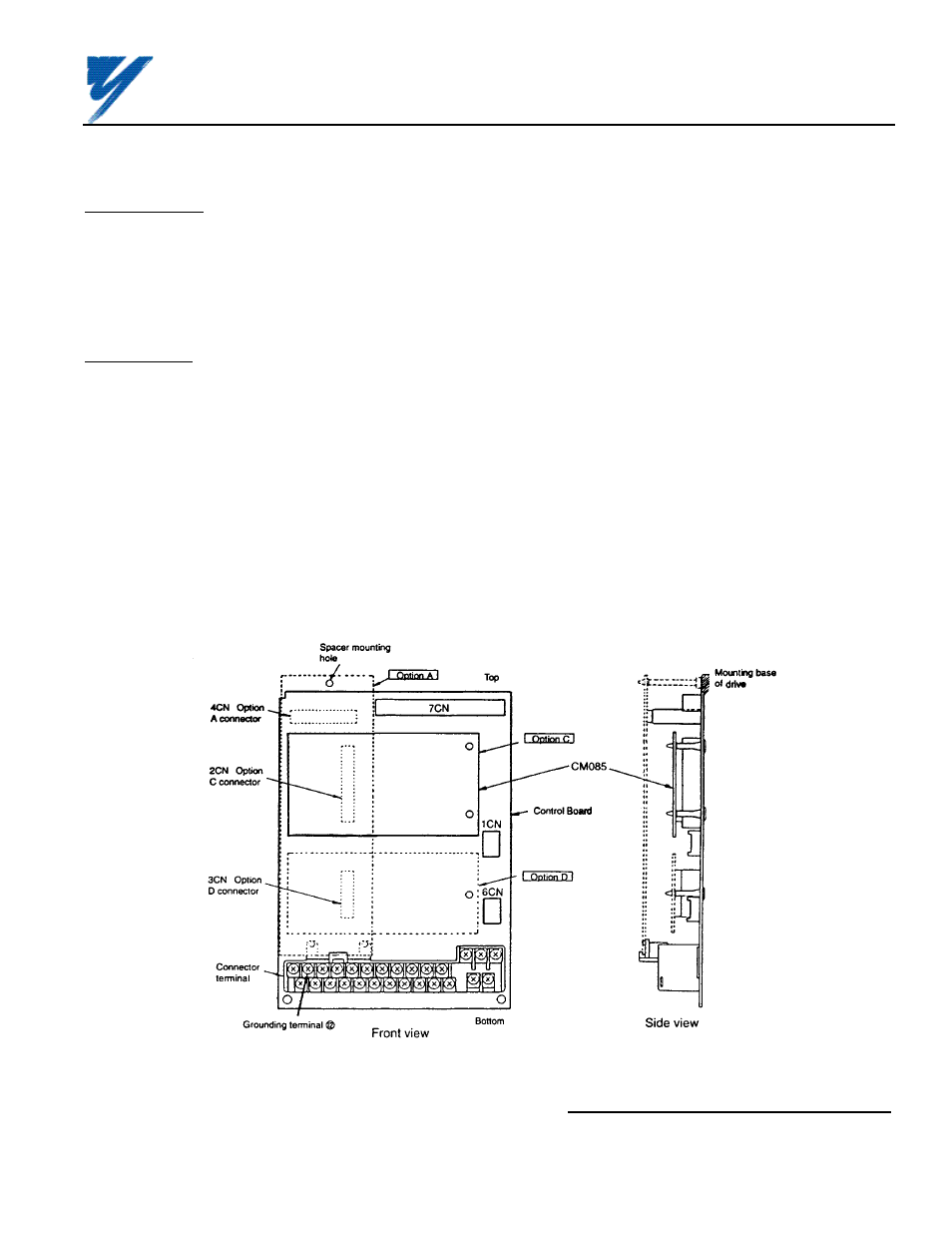
A4. See Figure A1. Install the option on the Main Control Board, 1PCB, and ensure 2CN is properly connected.
Make sure Electrostatic procedure is followed.
Figure A1. Installation of Analog Speed Reference (AI-14B) in GPD 515/G5
Yaskawa Electric America, Inc-www.drives.com
02Y00025-0296 Page 2 OF 14
REL. 08/23/91
ANALOG SPEED REFERENCE
(BIPOLAR) (AI-14B) MODEL DS387