5 installation procedure – Yaskawa 120 Vac Digital Input User Manual
Page 17
5 Installation Procedure
YASKAWA TOEP YEAOPT 07 A1000 Option DI-101 120 Vac Interface Installation Manual
17
6.
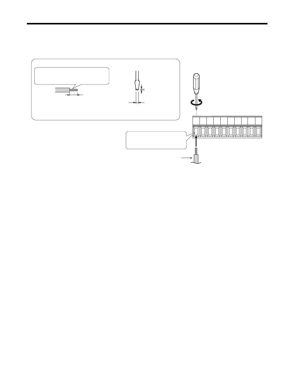
Prepare the external 120 Vac control circuit wires (customer supplied) for terminals
S1 to S8 and X2 on the DI-101 option as shown in
.
Figure 7
Figure 7 Preparing Cable Wiring
7.
Connect the customer wiring to the DI-101 option terminal block. Refer to
for a wiring diagram example showing customer interface circuitry.
Refer to Wire Gauges, Tightening Torques, and Crimp Terminals on page 20
to
confirm that the proper tightening torque is applied to each terminal. Take particular
precaution to ensure each wire is properly connected and wire insulation is not
accidentally pinched into electrical terminals.
WARNING! Fire Hazard. Tighten terminal screws to the specified tightening torque. Loose electrical
connections could result in death or serious injury by fire due to overheating. Tightening screws beyond the
specified tightening torque may cause erroneous operation, damage the terminal block, or cause a fire.
S1S2 S3 S4
X2
X2
S8
S7
S6
S5
DI-101 Option Terminal Block
Preparing wire ends:
Screwdriver blade size
about 5.5 mm (7/32”)
When not using
crimped insulated
sleeves
Strip wire insulation about 5.5 mm
and lightly twist the end with fingers,
keeping the ends from fraying.
Customer-supplied
120 Vac control circuit wires
(do not solder ends)
Loosen the screws and
insert the wire into the
opening on each terminal.
Blade depth of
0.4 mm or less
Blade width of
2.5 mm or less