R to, Figure 6, 5 installation procedure – Yaskawa 120 Vac Digital Input User Manual
Page 16
5 Installation Procedure
16
YASKAWA TOEP YEAOPT 07 A1000 Option DI-101 120 Vac Interface Installation Manual
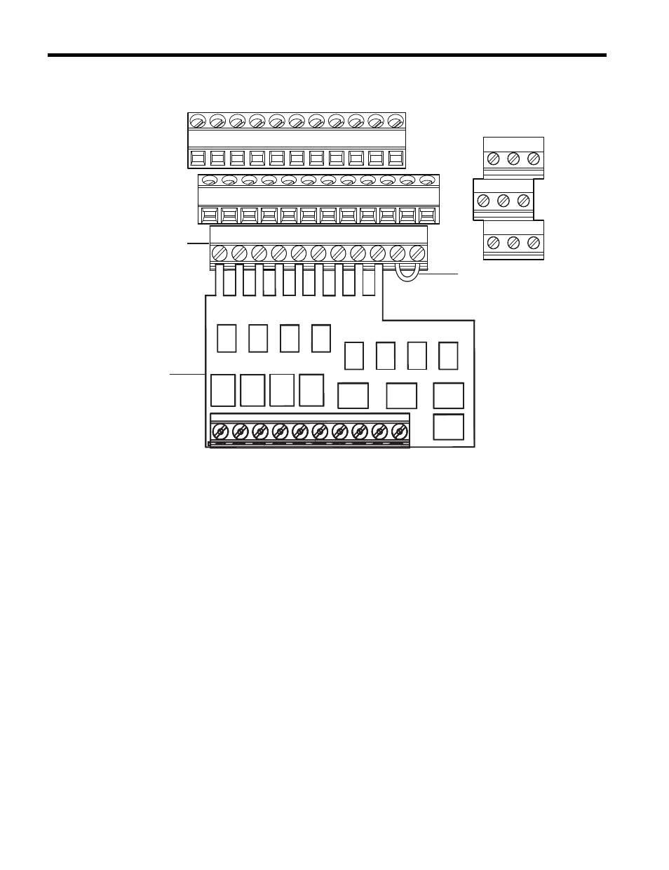
Figure 6
Figure 6 DI-101 Option to Drive Connection
5.
Ensure the factory installed wire jumper is present between TB1 terminals SC to SP.
If no wire jumper is present, prepare and install a jumper according to
Route the customer-supplied option wiring through one of the cable glands on the
A1000 drive bottom conduit bracket.
DI-101
Option
A1000 Drive Terminals
Terminal Block
TB1
Wire Jumper
MA MB MC
M1 M2 M5
M3 M6 M4
E(G) HC H1 H2 DM+ DM- IG R+ R- S+ S-
SC SP
V+ AC V- A1 A2 A3 FM AM AC MP RP AC
S1 S2 S3 S4 S5 S6 S7 S8 SN
S1 S2 S3 S4 S5 S6 S7 S8 SN
This manual is related to the following products: