2 connecting the power cables in the right system – SMA SC 630HE-11 User Manual
Page 5
SMA Solar Technology AG
Mounting and internal cabling
Installation Guide
5/5
SC_Chem_Aktiv-IEN092911
3.3.2 Connecting the power cables in the right system
1. Connect L1 at the lower power unit in the inverter cabinet.
2. Insert L1 through the cable gland A.
3. Connect L1 at the sine filter in the AC cabinet according to the label.
4. Tighten the cable gland A.
5. Connect L3 at the middle power unit in the inverter cabinet.
6. Insert L3 through the cable gland B.
7. Connect L3 at the sine filter in the AC cabinet according to the label
8. Tighten the cable gland B.
9. Connect L2 at the upper power unit in the inverter cabinet.
10. Insert L2 through the cable gland C.
11. Connect L2 at the sine filter in the AC cabinet according to the label.
12. Tighten the cable gland C.
☑ The power cables are connected.
3.4 Connecting the control cables to the transfer terminal strip in
the AC cabinet
Laying cables
The power cables must be bundled in the inverter cabinet by using cable ties. This prevents
the cables from being damaged by pointed or sharp metal edges.
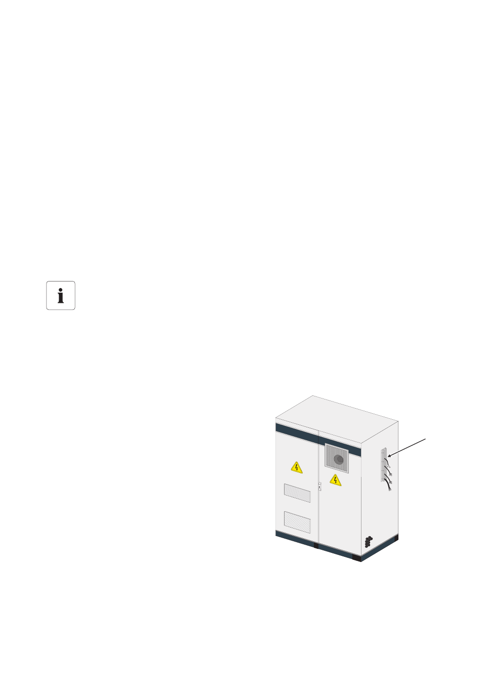
The control cables (A) are routed to the outside of the
DC/inverter cabinet during factory production.
1. Insert the control cables into the jacks in the AC
cabinet as described in the Sunny Central Installation
Guide.
• Make sure the plugs are not swapped.
☑ The control cables are connected.
A